Abstract
Digital holography has indeed led to numerous advancement of the classical, analog holographic technology that only permits a hologram to be permanently recorded onto a photographic film. In digital holography, a hologram can be captured from a real object. It can also be numerically generated as an array of numbers that can be stored as digital data, processed through computation, and distributed via digital communication links. In general, the primary purpose of holograms is to display 3-D images. Hence, a digital hologram in digital data form will not be of much practical use if it cannot be visually seen as a 3-D image. This is one of the major disadvantages of a digital hologram compared with the optical hologram, which can be readily captured with our eyes. However, a digital hologram can have different applications apart from generating 3-D images. In fact, recent research has shown that a digital hologram can be utilized in protecting sensitive data (a task referred to as cryptography), or in steganography for embedding large amount of additional data. This chapter describes some of the important applications of digital phase-only holograms in 3-D display, holographic cryptography, and steganography.
5.1 Introduction
Digital holography has indeed led to numerous advancement of the classical, analog holographic technology that only permits a hologram to be permanently recorded onto a photographic film. In digital holography, a hologram can be captured from a real object. It can also be numerically generated as an array of numbers that can be stored as digital data, processed through computation, and distributed via digital communication links. In general, the primary purpose of holograms is to display 3-D images. Hence, a digital hologram in digital data form will not be of much practical use if it cannot be visually seen as a 3-D image. This is one of the major disadvantages of a digital hologram compared with the optical hologram, which can be readily captured with our eyes. However, a digital hologram can have different applications apart from generating 3-D images. In fact, recent research has shown that a digital hologram can be utilized in protecting sensitive data (a task referred to as cryptography), or in steganography for embedding large amount of additional data. This chapter describes some of the important applications of digital phase-only holograms in 3-D display, holographic cryptography, and steganography.
5.2 Holographic Projection and Display
Modern computing technologies have enabled digital holograms to be generated with a commodity computer at video rate of over 25 frames per second. One may wonder why a holographic display unit is unavailable on the consumer market. The bottleneck in the popularity of holographic displays is caused by two major problems. First, a hologram is a complex-valued image composed of magnitude and phase components, and existing display devices can only present either the magnitude or the phase component. Second, holographic images comprise high-frequency fringes with the spatial frequency of optical waves. For the visible light spectrum, the wavelength of light is within the range [380 nm, 720 nm]. As such, the spatial period of fringes in a hologram of acceptable quality has to be under 10 μm, which is significantly less than the pixel size (roughly in the range 50–200 μm) of consumer-grade electronic displays (such as computer monitors and mobile phones).
The guiding objective of this book is to describe different methods developed to date for producing phase-only holograms, addressing the first problem mentioned above. For the second problem, so far digital holograms can only be displayed on special high-resolution devices that are commonly referred to as spatial light modulators (SLMs). Current SLMs are relatively small, in the order of a few centimeters, but are expensive. It will take years for them to evolve to a comparable size to televisions or computer monitors and to become a consumer commodity. Nevertheless, an SLM is still an effective tool for advancing the frontier of holographic technology. This section will describe the experimental setup and the important factors in displaying holograms on an SLM.
5.2.1 Spatial Light Modulator
“Spatial light modulator” is a general term for devices that are capable of modulating the amplitude, phase, or polarization of light. A typical SLM consists of a 2-D rectangular array of cells (pixels). The optical properties of light passing through or reflecting from each cell can be individually controlled by applying an external electrical signal. There are two major types of SLMs. The first one is based on translucent liquid crystal (LC) devices that modulates the light passing through them. The second type, SLM with liquid crystal on silicon (LCoS), reflect and modulate the light that impinges on it. The quality of an SLM is evaluated with a set of parameters obtained through a number of measurements. These parameters, listed and described in Table 5.1, are crucial in a holographic display system.
Table 5.1 Major specification of an SLM
For effective holographic display, an SLM should have a large dimension, small pixel pitch, short response time, high light utilization efficiency, and large fill factor.
Liquid crystal on silicon devices are commonly used in modern overhead projectors, and it is a preferable technology compared to LC devices due to its larger fill factor and higher light utilization efficiency. There are numerous LCoS-based SLM products available on the market, with large deviations in their technical specifications. Some of the popular suppliers include, but are not limited to, Hamamatsu Photonics, Holoeye Photonics AG, and the Jasper Display Corp.
A typical LCoS SLM device consists of a layer of liquid crystal material sandwiched between silicon and glass substrates. The silicon substrate is a 2-D rectangular array of pixel electrodes, and an active matrix circuit is embedded to control the electrical field injected to individual pixel electrodes. When the electric field of a particular pixel electrode is adjusted, the birefringence, and hence the phase retardation of the liquid crystal above the electrode, will change accordingly. A simplified structure of the LCoS SLM is shown in Figure 5.1.
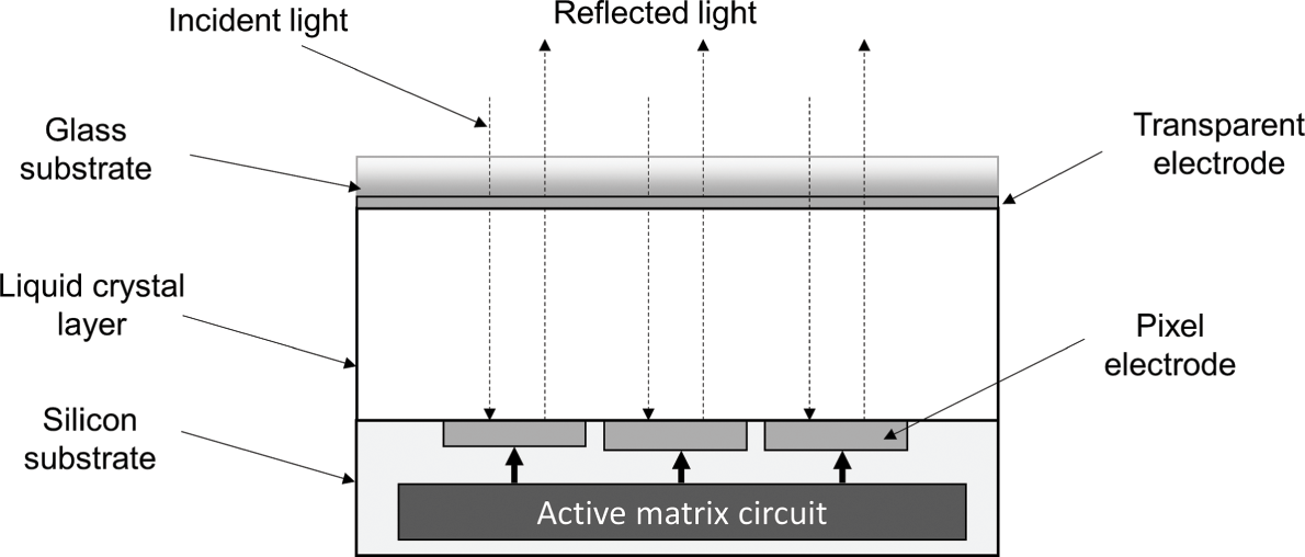
One can easily infer that if the electrical field of the active matrix circuit is adjusted to make the phase-shifting of the 2-D array pixels in the SLM similar to that of a phase-only hologram, the light reflecting from it will reconstruct the 3-D image that is represented by the hologram.
Basically there are two modes of optical reconstruction of a hologram by an SLM. The first mode is holographic projection, whereby the diffracted optical waves emitted by the hologram are projected onto a screen to show the reconstructed image. The screen can be a plane that is parallel to the hologram, or a 3-D surface. If a divergent beam illuminates the hologram, the size of the projected image will increase linearly with the distance between the screen and the hologram. On the other hand, if a plane wave is used instead of a divergent beam, the size of the projected image will be similar in size to the SLM, independent of the location of the screen. In both cases, the hologram should be generated in a way that the reconstructed image is in focus on the entire screen. For a planar screen that is parallel to the hologram, the focused plane is set to be at the location of the screen.
In the second mode of optical reconstructed images, the hologram is displayed as a visible 3-D image on the SLM. These two modes of hologram reconstruction will be described in the subsequent part of this section. To enhance the quality of the reconstructed image, the size of a hologram should be large, and the resolution should be high. A large SLM with fine pixel size, therefore, is desirable for displaying a hologram. The size and resolution of an SLM can be expressed by a dimensionless term known as the space–bandwidth product (SBP). The SBP is the product of the display area and the resolution of an SLM. Suppose an SLM device comprises of M columns and N rows of pixels, each being a square cell of side length δd meters. The size and bandwidth of the SLM are (Mδd×Nδd)
 m2, and (δd)−1
 for both dimensions, resulting in SBP = (Mδd×Nδd)(δd)−1(δd)−1
 = (M×N).
5.2.2 Holographic Projection
A typical optical setup for holographic projection with a phase-only hologram and a phase-only LCoS SLM is shown in Figure 5.2(a). Assuming a planar screen that is parallel to the hologram, a phase-only hologram is generated from a given source image located at a distance z from the hologram plane. It is then displayed on a phase-only SLM. Next, a point laser beam is converted into an optical plane wavefront with a beam expander, and taken to illuminate the SLM through the beam splitter. Each pixel on the SLM, upon impinging by the incoming beam, scatters a wavefront that is modulated by a phase-shift equivalent to that of the hologram pixel it represents. A screen is placed at a distance z from the hologram to show the projected image, which is sometimes referred to as a “real image.” The collection of optical wavefronts of all the pixel electrodes is reflected by the beam splitter, forming a focused optical reconstructed image on the screen. In this configuration, the illumination beam, the axial direction of the hologram, and the projected image are situated along the same optical path. As such, it is referred to as an inline holographic projection system.

Figure 5.2 (a) An inline holographic projection unit. (b) An off-axis holographic projection unit.
A major disadvantage of the setup in Figure 5.2(a) is that the illumination beam and the optical waves emitted by the SLM are attenuated by the beam splitter. This will lead to a dim reconstructed image as a large proportion of the optical beam has been diverted to other locations. An alternate setup to overcome this problem is to adopt the slightly off-axis arrangement, as in Figure 5.2(b). The optical paths of the illumination beam and the holographic waves are separated. In this off-axis arrangement, the reconstructed image is brighter as the expanded laser beam is used to illuminate the hologram directly.
5.2.3 Holographic Display
A holographic projector is similar to a traditional projector; the main difference is that the focusing of the projected image is produced by the computation of the hologram rather than by using an optical lens. For holographic projection, the focusing surface on which the reconstructed image is formed is fixed by the geometry of the screen. As such, a holographic projector is limited to showing a 2-D image when it is projected onto a flat surface, rather than the full functionality of a hologram’s true 3-D image. This limitation can be overcome with a 3-D holographic display, whereby the reconstructed image of a hologram is conveyed as a “virtual image,” rather than a “real image.” In a holographic projector, a real image is projected from the hologram onto a screen, forming a visible image. A virtual image is a 3-D image that is formed behind the hologram. Observing a virtual image is like looking at a 3-D scene through a window, with the viewing zone limited by the coverage of the SLM. As an observer views through the window at different angles, different parts of the 3-D scene will become visible. In addition, when the viewpoint is shifted, the disparity between objects at different depths in the scene will also change, as if the observer is looking at a real physical environment.
5.3 Holographic Encryption
After learning the primary role of phase-only holograms in image projection and display, we shall now have a look at some practical applications of phase-only holograms in cryptography. Cryptography, also known as encryption, is the art of changing numerical data to a form that can be interpreted by someone with the knowledge of how to revert the changes. It is an important technology for protecting private information from illegitimate access. Modern internet technologies, such as cloud and optical networks, are fully capable of storing and delivering big data sets that are highly vulnerable to security threats and malicious attacks. The problem is particularly critical when the service provider is an unknown common third party, whereby data could be eavesdropped upon during the course of distribution. If a communication link is being eavesdropped upon, all the sensitive contents in the data stream will be exposed, which can lead to severe security and financial impacts. To prevent this, cryptography is mandatory for maintaining the confidentiality of sensitive data and preventing it from being deciphered by unauthorized parties. Data that has been encrypted is generally known as ciphertext. Over the years, numerous research attempts have been conducted in the area of cryptography, resulting in different forms of realization, and some of them are rather complicated. The basic concept of cryptography is illustrated and explained with the simple block diagrams in Figure 5.3.

Figure 5.3 Fundamental framework of cryptography.
Cryptography comprises two parts. The first part is known as the encoder, which converts the source data into a ciphertext using a secret encryption key KE. The key can be in many forms, such as an image, a character string, or a mathematical operation on the input data. The goal is to generate a ciphertext that is significantly different from, and cannot be easily reverted back to, the source data. The second part of cryptography, known as the decoder, carries out the decryption process to revert the ciphertext to the source data with a decryption key KD. Most encryption methods are symmetric, meaning that the encryption and decryption keys are identical (i.e., KD= KE). If the encryption key is exposed, the source data can be easily obtained from the ciphertext. Many intruders, commonly known as cryptanalysts, have been attempting to deduce the secret keys of different encryptions through hacking attacks.
A well-known approach to deduce the encryption key in symmetric encryption is the “known plaintext attack” (KPA), with which the secret key (which is the same in both encryption and decryption) is deduced from the relation between a known source data set and its ciphertext. For example, a simple encryption that is performed by changing each value in the data set S=[32,−200,32,−128,−200,32,32,−128] into a different one, resulting in the ciphertext Se=[−16,112,−16,5,112,−16,−16,5]
 . The encryption/decryption key is a mapping between the original values S=[32,−200,32,−128,−200,32,32,−128]
 with the modified values [−16,5,112]
 . Suppose the source data and the ciphertext are both available, the secret key can be easily derived by comparing each element in S
 with its corresponding counterpart in the ciphertext Se
 .
.
Optical encryption is a variant of classical encryption, mainly applied in encrypting images. Instead of encrypting the source image directly, optical encryption methods are based on modifying the optical waves of a source image along its path of propagation. This approach is more secure than classical encryption, as the optical waves of a source image can be very different from the image itself. Hence even if the source image and its ciphertext are both available, it will be improbable to deduce the modifications that have been made to the optical waves emitted by the source image. Holographic encryption is a kind of optical encryption, whereby the hologram of the source data is encrypted. In this chapter we focus on holographic encryption of phase-only holograms. A hologram is basically used to represent pictorial information; to be explained later, it can also be employed to store and encrypt digital data.
5.3.1 Optical Cryptography
Most of the traditional encryption methods developed to date are designed to operate on the raw data directly. As mentioned before, such a kind of encryption can be cracked using KPA. In the past few decades, rapid advancements in optics have led to the emergence of optical encryption, adopting the theory of optics. Being different from data encryption in general, optical encryption is primarily used to encrypt optical images such as digital photographs. Despite the restricted scope of application, image encryption is important nowadays as there is a huge amount of image data transactions in contemporary social networks, wireless channels, and video broadcasting media. In optical encryption, the image to be encrypted is illuminated with a light source and the optical waves emitted from it are modified (based on an encryption key) at certain point(s) in the course of propagation toward a target destination. Grossly speaking, it is the light waves of the image, rather than the image itself, that are encrypted. Holographic encryption is a kind of optical encryption in which the wavefront selected for encryption is a hologram of the source image. A hologram is a 2-D complex image representing a 3-D image. Commonly, a hologram image comprises high-frequency fringe patterns that offer little clue on the image they represents. It is thus improbable to deduce the encryption key based on the ciphertext and the source image of a hologram.
5.3.2 Double Random Phase Optical Encryption
Effective optical/holographic encryption techniques developed to date are mostly based on the double random phase encoding (DRPE) framework. The method was first developed and reported by Philippe Refregier and Bahram Javidi in 1995 [1]. It is mainly used for encrypting optical images with which the light wave is encrypted in the spatial domain, and subsequently in the frequency space. The schematic of DRPE encryption is shown in Figure 5.4(a).

The source image I(m,n) to be encrypted is illuminated with an on-axis coherent plane wave. The optical wave emitted by the source image is passed through a random phase mask M1(m,n)=eiφ1(m,n)
 ( φ1(m,n)
 is a random quantity within the range [0,2π)
 ), which is taken to be the first encryption key. The light wave after passing through the random phase mask, given by IN(m,n)=I(m,n)eiφ1(m,n)
 , is Fourier transformed to its frequency spectrum IN˜(ωm,ωn)
 with lens L1. A random phase mask, M2(ωm,ωn)=eiφ2(ωm,ωn)
 , taken as the second encryption key, is placed at the Fourier plane containing the spectrum of IN(m,n)
 . Finally, the noise-added spectrum, denoted by IN˜(ωm,ωn)eiφ2(ωm,ωn)
 , is inverse transformed into the spatial domain with lens L2, resulting in a DRPE ciphertext C(m,n)
 . Denoting the forward and inverse Fourier transform operations as ℱ
 and ℱ−1
 , respectively, the ciphertext is given by
 (5.1)
(5.1) The decoding process is simply the reversal of the encryption, as shown in Figure 5.4(b). The ciphertext is illuminated with a coherent plane wave, and the optical wave emitted from it is converted into the frequency spectrum with lens L1. A phase mask M2†(ωm,ωn), which is the conjugate of M2(ωm,ωn)
 , is placed on the Fourier plane. Upon exit from the phase mask, the light wave is inverse Fourier transformed to give a decrypted image ID(m,n)
 on the image plane. Mathematically:
 (5.2)
(5.2) With the use of a digital CCD camera, the magnitude of the decrypted image, given by I(m,n)2 , is recorded.
The DRPE has two major disadvantages. First, the optical setups of the encoder and the decoder are quite complicated, as part of the process has to be conducted in Fourier space. Second, according to the evaluation on the methods in [2–9], the DRPE is vulnerable to different kinds of attacks. In particular, if the encoder is available, the encryption keys can be deduced with the chosen plaintext attack (CPA) and/or the KPA. In these two kinds of attacks, the source images and the ciphertexts are both available, and the encryption key can be revealed by analyzing the relation between them. According to [9], the random phase mask M2(ωm,ωn) could be easily deduced from the ciphertext of a Dirac impulse (i.e., a single dot). There are different variations on the implementation of the DRPE method to increase its resistance to attacks, such as, but not limited to, phase reservation and compression [10], photon counting [11], space multiplexing of multiple images [12], fractional Fourier transform [13,14], randomized lens-phase function [15], and Arnold transform [16]. Apart from image encryption, DRPE has been extended to encrypt digital data by embedding it in a QR code [17,18].
5.3.3 Single Random Phase Holographic Encryption
Inspired by DRPE, a low-complexity holographic encryption method known as single random phase encryption (SRPE) was proposed in [19]. The concept of SRPE is shown in Figure 5.5(a). A 3-D source image is input to a stochastic hologram generator. In the generator, the source image is first modified in a random manner that retains its visual quality, and then placed in a larger global image G(m,n) . In the figure, the source image is scaled in size and added with a text message “ABC” that is not overlapping with the image. The modified image is then converted into a phase-only hologram HP(m,n)
 . By adding a random phase mask M(m,n)
 (the encryption key), the phase-only hologram is converted into a SRPE hologram HE(m,n)=
 HP(m,n)M(m,n)
 (ciphertext). As is explained in more detail later, the process is equivalent to a one-time pad encryption generally considered to be an “unbreakable” cipher method.

Figure 5.5 (a) Concept of the single random phase encryption (SRPE) method. (b) Implementation of the SRPE encoder. (c) Implementation of the SRPE decoder.
Implementation of the SRPE encoder and decoder is shown in Figures 5.5(b) and 5.5(c), respectively. In the encoder, the source image is embedded into a global image and converted into a phase-only hologram HP(m,n) . The latter is them overlaid with a random phase mask M(m,n),
 resulting in an SRPE hologram HE(m,n)
 . In the decoder, the encrypted hologram HE(m,n)
 is overlaid with a phase mask M†(m,n)
 , which is the complex conjugate of M(m,n)
 , thus recovering the phase-only hologram HP(m,n)
 of the global image. When HP(m,n)
 is illuminated with a coherent beam, the global image and the modified source image that is embedded in it will be reconstructed to form a visible image. Figures 5.5(b) and 5.5(c) show that the complexity of the SRPE method is substantially lower than the DRPE. However, since the ciphertext is representing the global image rather than the source image, it will be improbable to apply KPA or CPA to deduce the encryption key.
The SRPE method is simple in structure and has the following advantages:
1. The source image is modified in an unknown and random manner, so that encryption of the actual image is unknown. The absence of knowledge on what is represented by the phase-only hologram and its encrypted data makes it difficult to deduce the encryption key by plaintext attacks.
2. For the same input source image, a vastly different phase-only hologram results in each round of encryption. Hence, it is not possible to deduce the encryption key by analyzing the correlation (or difference) between a large set of similar source images and their corresponding ciphertexts.
3. After adding the random phase mask, which is taken as the encryption key, it is even more difficult to deduce the encryption key through analyzing the relation between the input image and the SRPE hologram.
4. Upon decryption, the perceptual quality of the original source image is chiefly preserved favorably even though a certain part of it has been distorted.
Following is an explanation of the detail formulation of the SRPE method, which can be divided into three stages.
Stage 1: Stochastic Modification of the Source Image
The source image is modified randomly in a manner that is unknown to the person encrypting the image. Assume the encryption device, whether it is implemented with software or hardware, is a black box so that the details within it are concealed from the operator. To avoid causing too much change to the source image, the random modification is limited to a moderate amount of geometrical transformation (such as scaling and translation). After modifying the source image I(m,n) , it will be pasted into an arbitrary position in a larger global image G(m,n)
 . The rest of the areas in the global image that are not occupied by the source image will be filled with randomly generated content P(m,n)
 . Mathematically, the global image is given by
 (5.3)
(5.3) where T[] represents some form of geometrical transform. Equation (5.3) constitutes a stochastic modification of the source image, so that the global image is substantially different from the original source image. The global images generated in different runs of the encryption process will also deviate from one another. This mechanism ensures that neither the cryptanalyst nor the one who performs the encryption will have knowledge of what is being encrypted. Without information on the source data, it will be improbable, if not impossible, to draw any relationship between the ciphertext and the source image. By the same argument, the stochastic modification will also prevent the encryption key from being exposed through large-scale CPA, as the images being utilized to probe the encryption engine will also change in an unknown manner prior to their encryption.
Stage 2: Converting the Global Image to a Phase-Only Hologram
The global image is first converted to a digital Fresnel hologram by convolving the global image with free space impulse response of the light propagation h(m,n;z0) as
as
 (5.4)
(5.4) The free space impulse response of light propagation is given by h(m,n;z0)=iλz0exp{i2πλ(mδd)2+(nδd)2+z02} , where λ
 is the wavelength of light, and δd
 is the pixel size of the hologram. As the hologram is generated from the global image, it is referred to as the global hologram.
The complex-valued hologram H(m,n) is then converted into a global phase-only hologram HP(m,n)=exp[iθ(m,n)]
 with either uni-directional or bi-directional error diffusion.
Stage 3: Encrypting the Phase-Only Hologram with a Random Phase Mask
In this final stage, a random phase mask M(m,n)=exp[iφ(m,n)] (where φ(m,n)
 is a random value in the range [0,2π)) is overlaid onto the global phase-only hologram, resulting in an encrypted hologram
 (5.5)
(5.5) In the decoder, as shown in Figure 5.5(c), the global phase-only hologram is recovered by overlaying the conjugate of the random phase mask M(m,n) onto HE(m,n)
 :
:
 (5.6)
(5.6) The random phase mask M(m,n) can be taken as the secret key for encrypting and decrypting the global image, which is different from the source image I(m,n)
 . Hence, given I(m,n)
 and HE(m,n)
 , it is not possible to deduce the secret key M(m,n)
 . After decryption, the global image can be reconstructed from the hologram through optical or numerical reconstruction. From the reconstructed global image, the source image, which is separated from the randomly added contents, will appear with good visual quality.
Numerical simulation of the SRPE method is conducted with the source code in Section 5.5.1. The source image “Fish_1” in Figure 5.6(a) is embedded into the larger canvas “Canvas” comprising of a QR code and a text message “Single random phase encryption,” resulting in a global image as shown in Figure 5.6(b). A phase-only hologram HP(m,n) is generated from the global image with uni-directional error diffusion and infused with random phase noise M(m,n)
 to give an SRPE hologram HE(m,n)
 , as shown in Figures 5.6(c). The SRPE hologram is decoded by being overlaid with the conjugate of the random phase mask M†(m,n)
 , and the reconstructed image is shown in Figure 5.6(d). It can be seen that apart from some mild noise contamination, the reconstructed image is similar to the original one.

Figure 5.6 (a) Source image “Fish1.” (b) Global image. (c) SRPE hologram of the global image. (d) Reconstructed image of the decoded SRPE hologram on the focused plane.
5.3.4 Enhanced Single Random Phase Holographic Encryption
Despite the effectiveness of SRPE, the source image is modified after encryption. Although the modification does not affect the visual quality, it may not be acceptable in some applications. In view of this, enhanced single random phase encryption (ESRPE) was proposed in [20]. In comparison with SPRE, the ESRPE has similar advantages, but will not lead to any alteration to the source image.
The ESRPE method comprises four stages, as shown in Figure 5.7 and outlined here.

In the first stage, the source image I(m,n) to be encrypted is converted into an off-axis complex hologram based on angles of incidence θm
 (along the horizontal direction) and θn
 (along the vertical direction). If θm
 = 0 and θn=0
 , the complex hologram is equivalent to an on-axis or inline hologram. The source image can be a planar image or a 3-D image. When the off-axis hologram of the source image is illuminated with a plane wave, the source image will be reconstructed on the focused plane oriented at angles θm
 and θn
 along the horizontal and vertical directions, respectively, from the normal of the hologram plane. The hologram being generated from the source image is known as the source hologram.
In the second stage, one or more secondary images Ik(m,n)|1≤k≤K (where K≥1
 is the total number of secondary images) are randomly generated or selected from a pool of images that is unknown to the operator, and are converted into an off-axis complex hologram. For simplicity of illustration, only one secondary image I1(m,n)
 is shown in Figure 5.7. Each off-axis hologram is generated based on a reference beam at an angle of incidence θk;m
 (along the horizontal direction) and θk;n
 (along the vertical direction). When the off-axis hologram of the secondary image is illuminated with a plane wave, the secondary image will be reconstructed on the focused plane oriented at angles θk;m
 and θk;n
 along the horizontal and vertical directions, respectively, from the normal hologram plane. The hologram being generated from a secondary image is known as the secondary hologram. The same applies if there is more than one secondary image, in which case there will be a set of secondary images with corresponding secondary holograms.
In the third stage, the source hologram and the secondary hologram(s) are summed up into a global hologram HG(m,n) and converted into a global phase-only hologram HP(m,n)
 with existing techniques such as, but not limited to, error diffusion [21,22]. The global phase-only hologram is very different from the source hologram and any of the secondary hologram(s). As the secondary image is randomly generated or selected from unknown sources, even for identical source images, a totally different global phase-only hologram will be generated in each run of the encryption process.
In the fourth stage, a random phase mask M(m,n)=eiφ(m,n) is added to the global phase-only hologram HP(m,n)
 , resulting in an ESRPE hologram HE(m,n)
 . The latter is a ciphertext hologram that bears little correlation to the source image or the secondary image(s).
The mixing of the holograms of the source image and one or more secondary images ensures no prior knowledge of what is being encrypted, so that there is no direct relation between the ESRPE hologram and the source image. It also increases the difficulty of deducing the encryption key through large-scale CPA (e.g., encrypting a large number of source images, each with a small amount of incremental change, to locate the affected regions of the ciphertext hologram).
In the decoder, the ESRPE hologram is overlaid with the conjugate of the random phase mask (encryption key) and illuminated with a coherent beam. The source and the secondary images will be reconstructed at the focused plane along orientations HE(m,n) and (θk;m,θk;n)
 , respectively. If the angular separation between (θm,θn)
 and the orientation(s) of the secondary holograms (θk;m,θk;n)
 is large enough, the images will be formed at non-overlapping areas on the focused plane, and the source image can be observed visually at its original position without any geometrical change. The specific formulation of each stage of the proposed method is described in the following sub-sections.
Stage 1: Converting the Source Image into an Off-Axis Hologram
For simplicity of explanation, the source is assumed to be a 2-D planar image I(m,n) , which is parallel to and at an axial distance z0
 from the hologram. The source image is first converted into an off-axis complex Fresnel hologram H(m,n)
 ; R(m,n)
 is an inclined plane wave with an angle of incidence (θm,θn)
 .
.
 (5.7)
(5.7) where R(m,n) is an inclined plane wave with an angle of incidence (θm,θn)
 .
.
Stage 2: Converting Secondary Images into an Off-Axis Hologram
The secondary images are assumed to be 2-D planar images Ik(m,n)|1≤k≤K , which are parallel to and at an axial distance zk
 from the hologram. However, more secondary images can be added by the same principle. Similar to stage 1, an off-axis hologram Hk(m,n)
 is generated for the kth secondary image with the angle of incidence of the plane wave Rk(m,n)
 at angles of incidence (θk;m,θk;n)
 .
.
Stage 3: Generating a Global Hologram
In this stage, the source and the secondary holograms are integrated into a new hologram HG(m,n) :
:
 (5.8)
(5.8) Subsequently, HG(m,n) is converted into a global phase-only hologram HP(m,n)
 with the error diffusion method. In HP(m,n)
 , the magnitude of all the pixels is set to a constant value.
Stage 4: Converting the Global Hologram into a ESRPE Hologram
Finally, the global hologram is multiplied with a random phase mask M(m,n)=eiφ(m,n) , resulting in an ESRPE hologram given by
 (5.9)
(5.9) The ESRPE hologram is taken as the encrypted (ciphertext) hologram, with the phase mask eiφ(m,n) as the private encryption key. When the ciphertext hologram is overlaid with the conjugate of the phase mask, and illuminated with a coherent beam, the global image, comprising the source image and the secondary image(s), will be reconstructed. The decryption process can be conducted through optical or numerical reconstruction as
 (5.10)
 Numerical simulation on the ESRPE method is conducted with the MATLAB code in Section 5.5.2. The source image “Fish_2” and a secondary image “Flower_1” are shown in Figures 5.8(a) and 5.8(b), respectively. Both images are located at an axial distance of 0.3 m from the hologram plane. An inline hologram is generated for the source image, and an off-axis hologram is generated for the secondary image with (θk;m,θk;n)=(0.8°,0°) . A global hologram is obtained by summing up the holograms of the source and the secondary images. The global image is then converted into a phase-only hologram with uni-directional error diffusion, as shown in Figure 5.8(c), and mixed with a random phase mask M(m,n)
 into an ESRPE hologram HE(m,n)
 in Figure 5.8(d). Subsequently, the ESRPE hologram is decoded by integrating the conjugate of the random phase mask and the reconstructed image of the decoded hologram HP(m,n)
 on the focused plane, as shown in Figure 5.8(e). The reconstruction of the source and the secondary images are separated from each other, and yet the reconstructed source image is similar to the original one, as illustrated in Figure 5.8(f).

Figure 5.8 (a) Source image “Fish_1.” (b) Secondary image “Flower_1.” (c) Global phase-only hologram representing the source and the secondary images. (d) ESRPE hologram. (e) Reconstructed image of the decoded ESRPE hologram on the focused plane. (f) Enlarged view of the reconstructed source image.
5.3.5 Multiple-Image Holographic Encryption with Arnold Transform
In SRPE and ESRPE, an encrypted image can be decrypted and reconstructed optically as a visible image through overlaying the conjugate of the phase mask on the encrypted hologram. These two methods are only effective in encrypting a single source image. More sophisticated encryption of multiple images in a single phase-only hologram can be accomplished if part of the encoding and decoding process can be conducted numerically. Recently, a method has been proposed in [23] for encrypting multiple images in a single phase-only hologram by incorporating the Arnold transform. Briefly, Arnold transform is a reversible chaotic mapping of a torus into itself. The Arnold transformed data set can be fully recovered through an inverse process. This technique can be widely applied in scrambling, encryption, and data hiding [24–26]. Referring back to the method in [23], a set of source images are each converted into a hologram with the grid-cross downsampling (GCD) method, and transformed with the Arnold transform with a unique number of iterations. The Arnold transformed holograms are summed up into a single integrated hologram, and the phase component is retained as an integrated sampled phase-only hologram (ISPOH) that encrypts all the source images. To recover a particular image, the integrated phase-only hologram is decrypted by applying the inverse Arnold transform with the corresponding number of iterations. As the holograms of the source images are generated with the GCD method, the decrypted image can be observed by simply illuminating the phase-only hologram with a coherent beam.
The encryption and decryption process is as follows. The encryption process comprises three stages, as illustrated in Figure 5.9(a); the decryption process is shown in Figure 5.9(b). First we shall study the encryption process. A set of K images, denoted by Sk(m,n)|1≤k≤K , is to be encrypted into a phase-only hologram HP(m,n)
 . For clarity and without loss of generality, the source images are assumed to be planar, parallel to the hologram, and located at an identical axial distance of z0
 from the hologram.

Figure 5.9 (a) Encrypting multiple images into a single integrated sampled phase-only hologram (ISPOH). (b) Decrypting the kth image from the ISPOH.
Stage 1: Generating Digital Fresnel Holograms With the Grid-Cross Downsampling (GCD) Method
One of the major objectives of the method is to encrypt the source images into a phase-only hologram, in order to display an image of reasonable visual quality with the decrypted hologram on a single phase-only SLM. To achieve this goal, the downsampling method is employed to generate the hologram of each source image. As the GCD method has been described in detail in Chapter 3, only a brief outline is given here. In the GCD method, the intensity of each image is downsampled with a grid-cross lattice prior to the conversion to a hologram.
Let τ and % denote the downsampling interval and the modulus operator, respectively, and the grid-cross downsampling lattice L(m,n)
 is,
is,
 (5.11)
 where p=(m%τ) and q=(n%τ)
 .
.
After downsampling the grid-cross lattice, the downsampled source images are given by
 (5.12)
 Next, each downsampled source image Ik(m,n) is converted into a Fresnel hologram Hk(m,n)
 by convolving with the free space spatial impulse response of propagation of light h(m,n)
 , resulting in a digital Fresnel hologram mathematically as
 (5.13)
 where * is the 2-D convolution operator and h(m,n;z0)
 is the free space impulse response of light propagation.
Stage 2: Multiple Arnold Transform of Holograms
In the first stage, holograms of different source images are generated with Fresnel diffraction, to be combined into a single integrated hologram. However, the holograms cannot be directly summed up into an independent entity, as their contents will be merged and not separable in the future. Hence, in the second stage each of the holograms generated in the first stage is encrypted and merged with each other. The encryption is conducted with repetitive rounds of Arnold transforms (which is referred to as multiple Arnold transform) so that each individual hologram can be extracted in the decryption process. As reported in [27], the Arnold transform is a scrambling technique whereby the locations of pixels are shuffled through a 2-D transformation matrix. In each round of transformation, the position of each pixel of the current hologram is moved to a new position, resulting in a new hologram. In order to enable individual holograms to be extracted from the integrated hologram, it is mandatory that the number of rounds of Arnold transform should be different for each hologram. Consider the kth hologram Hk(m,n) of size N×N
 . Let HA;k(mj,nj)
 and HA;k(mj−1,nj−1)
 denotes the hologram after j
 and j−1
 rounds of Arnold transforms, respectively. A pixel at location (mj,nj)
 in HA;k(mj,nj)
 is copied from the pixel at location (mj−1,nj−1)
  of HA;k1(mj−1,nj−1)
 according to the following equation:

where A=[1abab+1] is the Arnold transform matrix, and (a, b) = (2,1) are the transform parameters.
The pixel locations in an Arnold transformed image can resume their original positions with an inverse Arnold transform, given by
 (5.15)
 Applying the inverse Arnold transform to the hologram HA;k(mj,nj) , the pixels of hologram HA;k(mj−1,nj−1)
 can be deduced from the following expression:
 (5.16)
 As an example, a pixel at (mj−1,nj−1)=(100,50)  at the (j−1)th
 iteration with N=128
 will be relocated to a new position at (mj,nj)=(72,122)
 after applying a single round of Arnold transform. The pixel can be returned to its original position with the inverse Arnold transform.
Let ek denote the number of Arnold transforms that have been applied to the kth hologram. The transformed hologram is represented by HA;k(mek,nek)
 . In order to retain the individuality of each hologram in the integrated hologram, the number of transforms applied to each hologram has to be different: eA=eB⇔A=B
 .
.
Stage 3: Generating the ISPOH
In this final stage, the Arnold transformed holograms are integrated into a single integrated hologram given by
 (5.17)
 Subsequently, the phase component of the integrated hologram is retained as the ISPOH HP(m,n) :
:
 (5.18)
 where arg[] denotes the argument – that is, the phase component of the bracketed complex quantity. The value ek
 , which corresponds to the number of Arnold transforms on the kth hologram, will be taken as the unique key parameter for retrieving the kth hologram from the ISPOH.
The decoding process is shown in Figure 5.9(b). To retrieve the kth hologram from the ISPOH, ek rounds of inverse Arnold transforms are applied to the ISPOH HP(m,n)
 , resulting in a decoded phase-only hologram Gk(m,n)
 . Among all the holograms that have been encrypted in the Gk(m,n)
 , only the one corresponding to HA;k(mek,nek)
 can be reverted to an approximation of Hk(m,n)
 , denoting this hologram by Hk'(m,n)
 . This is mixed with the rest of the holograms, which are not inverse transformed with the correct number of rounds of inverse Arnold transform. When the decoded hologram Gk(m,n)
 is illuminated with a coherent beam, Hk'(m,n)
 will be reconstructed, with a certain amount of distortion caused by removal of the magnitude component, to an image Ik'(m,n)
 that is an approximation of the downsampled source image Ik(m,n)
 . The rest of the components in the ISPOH are reconstructed as noise data. Alternatively, Ik'(m,n)
 can also be derived numerically through convolving k(m,n)
 with h†(m,n;z0)
 , the conjugate of the free space impulse response, as given by
 (5.19)
 To further reduce the noise contamination, as well as avoiding the zero-order beam in optical reconstruction, the decoded hologram Gk(m,n) can be converted into an off-axis hologram Gka(m,n)
 by multiplying it with an inclined plane wave Rθr(m,n)
  as
as
 (5.20)
 where Rθr(m,n)=exp(i2πmλsinθr) .
.
The simulation on the multiple-image holographic encryption method is given in Section 5.5.3. Four source images Sj|1≤j≤4 , as shown in Figure 5.10(a–d), are employed to illustrate the method. Referring to the schematic in Figure 5.9(a), each image is downsampled with the grid-cross lattice with the factor τ=12
 , and converted into a 1024 × 1024 Fresnel hologram. The axial distance between the image and the hologram planes is 0.3 m for all the source images.
To combine the four holograms into a single one, each hologram is transformed with ej rounds of the Arnold transform. The value of ej
 is set to 10×j
 so that each hologram is transformed with a unique round of Arnold transforms. This will permit holograms to be separable from each other in the future. Next, the transformed holograms are integrated into a single hologram HI(m,n)
 , and an ISPOH Hph(m,n)
 is obtained by forcing the magnitude of all the pixels in HI(m,n)
 to unity.
In the decoding stage, the holographic information corresponding to the hologram of the jth image is recovered from Hph(m,n) with ej
 rounds of inverse Arnold transforms, resulting in the phase-only hologram Gj(m,n)
 . The numerical reconstructed images of the four holograms from Gj(m,n)|0≤j≤3
 are shown in Figure 5.10(e–h). Apart from the degradations being caused by the grid-cross downsampling of the source images and the removal of the magnitude component in the integrated hologram, the numerically reconstructed images are similar to the source images.


5.4 Holographic Steganography
Steganography is the art of concealing secret information, such as a message or an image, in another data set. However, since the host data set is modified after embedding the secret data, it is essential that the introduced changes do not cause observable differences. The embedding capacity, that is the amount of information that can be embedded into the host, is generally rather limited. Holographic steganography is embedding information in a hologram. As holograms are resistant to damage and capable of representing multiple images, the embedding capacity is significantly higher than that of an optical image such as a photograph. A number of methods for concealing information in a digital hologram are introduced in this section.
5.4.1 Data Embedded Error Diffusion Hologram
In Chapter 4 we saw that error diffusion is an effective means of converting a hologram into a phase-only hologram. Error diffusion is a local error compensation mechanism with which the error resulting from approximating a pixel in a certain way (e.g., converting it into a binary value) is distributed to other pixels in its vicinity. In converting a complex-valued hologram to a phase-only hologram with error diffusion, the magnitude of each hologram pixel is removed, and the error is added to the neighboring pixels. It has been proven that an error diffusion hologram is capable of preserving the source image with high quality, although only the phase component of the hologram is present. On this basis, a method was proposed in [28] for adding external data into a hologram, whereby the error resulting from the contamination and that arising from the removal of the magnitude component are combined and compensated with error diffusion. A phase-only hologram generated with this method is referred to as a data embedded error diffusion (DEED) hologram. Experimental results have demonstrated that a DEED hologram is capable of embedding an image that is of similar size to the hologram, and yet preserving favorable quality on both the hologram and the embedded image.
Generation of a DEED hologram is divided into three stages, as shown in Figure 5.11.

Figure 5.11 Schematic of the DEED hologram generation method.
Stage 1: Hologram Generation and Embedded Data Decomposition
In this stage, a digital Fresnel hologram H(m,n) is generated from a source image with Fresnel diffraction. For the sake of simplicity, we have assumed that the source image is planar and parallel to the hologram plane. The magnitude and phase components of H(m,n)
 , denoted by |H(m,n)|
 and ∠[H(m,n)]
 (where ∠[]
 denotes the phase angle of the complex variable within the square brackets), are normalized into the range [0,1]
 and [0,255)
 , respectively. As such, the phase angle of the hologram pixel is represented with eight bits. The embedded data is decomposed into a sequence of short chunks of data C=[c0,c1,…..cK−1]
 , each chunk being represented with bL
 bits, where bL<8
 , and queued into a first-in-first-out (FIFO) buffer. In the FIFO buffer, c0
 is the first member (head) and cK−1
 is the last member (tail) of the queue.
Stage 2: Data Embedded Error Diffusion
In this stage, the complex-valued hologram H(m,n)  is added to external data in a pixel-by-pixel manner and converted into a phase-only hologram HP(m,n)
 with uni-directional error diffusion. The hologram is scanned pixel by pixel from the first row to the last row, and from the leftmost column to the rightmost column in each row. The magnitude of each hologram pixel is set to unity and the phase component is retained, converting it into a phase-only hologram pixel. The latter is then split into a lower-ordered byte of bL
 bits and a higher-ordered byte of bH=(8−bL)
 bits. The head of the queue in the FIFO buffer is taken to replace the lower-ordered byte of the phase component. Subsequently, the head is removed from the FIFO buffer and the next member becomes the head of the queue. Suppose the current hologram pixel is located at the yj
 row and the xi
 column, and the current head of the queue is ck
 . The current hologram pixel will be converted into a phase-only value:
 (5.21)
 where bM is a binary string comprising bL
 bits of 0. An example is shown in Figure 5.12 with ∠[H(mi,nj)]=[11000101]
 , bL
, bL =4, and ck=[1100]
 . The revised pixel value is given by HP(mi,nj)=[11001100]
 .
.

Figure 5.12 Example showing embedding an external chunk of data into a phase-only hologram pixel.
The error resulting from converting the current hologram pixel into HP(mi,nj) is diffused to its four unvisited neighboring pixels.
The source code for generating the DEED hologram is shown in Section 5.5.4. In the simulation, a Fresnel hologram H(m,n) of the source image “Flower 2” in Figure 5.13(a) is generated. Next, uni-directional error diffusion is applied to convert the hologram into a phase-only hologram, and at the same time embedding it with a 2-D image “Grey,” shown in Figure 5.13(b). The reconstructed image of the DEED hologram and the embedded image corresponding to bL
 = 2 and 6 are shown in Figure 5.13(c. d) and 5.13(e, f), respectively.

Figure 5.13 (a) Source image “Flower_2.” (b) Embedded image “Grey.” (c) Reconstructed image of DEED hologram embedded with bL= 2 bits. (d) Reconstructed image of DEED hologram embedded with bL= 6 bits. (e) Image embedded in DEED hologram with bL= 2 bits. (f) Image embedded in DEED hologram with bL= 6 bits.
From the results shown in Figure 5.13(c–f), it can be seen that the quality of the reconstructed images improves with a lower number of embedded bits (i.e., a smaller value of bL ), but the other way round for the embedded image.
5.4.2 Image Embedded Error Diffusion Hologram
Section 5.4.1 shows that the DEED hologram is capable of embedding a certain number of data bits into each hologram pixel, at the expense of degrading the reconstructed image of the hologram. It is desirable to limit the bit length of the embedded data in each hologram pixel to fewer bits in order to preserve higher fidelity of the reconstructed image. The examples in Figure 5.13 reflect that if the embedded data is an image, its quality is rather poor if each of its pixels is truncated into 2 bits. This dilemma can be overcome if the data size of the image is reduced prior to embedding into a hologram, a process that is generally referred to as image compression. Attempts to address this issue have been reported in [29,30] based on block truncation coding and error diffusion. The following subsection explores these two methods and their performances, in terms of compression and fidelity, by reducing the data size of an image.
5.4.2.1 Block Truncation Coding
Block truncation coding (BTC) is a low-complexity image compression method that was developed by E. Delp and O. Mitchell in 1979 [31]. An image to be compressed is uniformly partitioned into non-overlapping square image blocks, and each block is compressed individually. The amount of computation is small, which is suitable for implementation with low-speed processors or hardware circuits. In general, an 8-bit gray level image can be compressed by four times with the BTC and still maintain high fidelity (in terms of PSNR) of over 30 db. As image blocks are compressed separately, the encoded data is highly resistant to damage and noise contamination. This implies that if a certain part of the compressed data is modified or lost, it will only affect the corresponding regions in the decrypted image, while the rest of the areas will remain intact. BTC can be divided into three stages as follows.
Stage 1: Block Partitioning
An input image I(m,n) is uniformly partitioned into non-overlapping square blocks of size τ×τ
 . For an image with horizontal and vertical extents of M
 and N
and N , respectively, the total number of image blocks in an image is MN/τ2
 , each composed of τ2
 pixels.
Stage 2: Mean and Standard Deviation Computation
In this stage, the mean and standard deviation of each image block is determined. Let bj denote the jth image block in the image. The mean μj
 and standard deviation σj
 of the jth image block are:
 (5.22)
 and
 (5.23)
 where bj(p,q) is the pixel on the qth row, and the pth column of block bj
 .
.
Stage 3: Encoding Pixels in Each Block
In this stage, each pixel in an image block is encoded into a binary bit of 0 if it is less than the mean and 1 if it is more, resulting in a block of binary pixels. For the jth image block, the encoded block cj is:
is:
 (5.24)
 Let ϵj denote the number of pixels with a value of 1 in cj
 ; a pair of values Uj
 and Lj
 are determined as
 (5.25a)
  (5.25b)
 The compressed data set of each image block is composed of the binary image block cj and the pair of values Uj
 and Lj
 . Suppose Uj
 and Lj
 are each represented by rj
 bits, the compressed image block contains (2rj+τ2)
 bits, and the average bit-per-pixel (bpp) is (2rj+τ2)τ2
 . The compression ratio of each image block, which is equivalent to that of the entire image, is:
 (5.26)
 where s is the number of bits for representing a pixel in the source image. For example, given s
 = 8, rj
 = 8, and τ=4
 , the bpp is (2×8+42)42=2
 , and the compression ratio is CR=8×42(2×8+42)=4
 times.
Decompression in BTC is rather straightforward, and conducted in a block-by-block manner. Each encrypted image block bj’ is reconstructed from its compressed data as

In general, BTC is capable of compressing images with good fidelity at a moderate compression ratio. Although the compression ratio is not as high as other sophisticated methods, such as JPEG and vector quantization, BTC has the advantage of being computationally efficient, especially for the decoding process, which can be accomplished with a very small amount of arithmetic and logical operations.
To illustrate the performance of BTC, it is applied to compress the image in Figure 5.13(a) and Figure 5.13(b) with s = 8, rj
 = 8, and τ=4
 . The decoded images, as shown in Figure 5.14, are almost identical to the original images. According to Eq. (5.26), the compression is four times, with each pixel represented by 2 bits.

Figure 5.14 Images in Figures 5.13(a) and 5.13(b) that have been compressed by BTC with a compression ratio of four times.
An example of embedding a BTC-encoded image into a binary hologram was demonstrated in [29].
5.4.2.2 Error Diffusion
Although BTC is an effective method of reducing the data size of the embedded image, the number of bits per pixel is always larger than one. This restriction can be overcome if the image can be compressed to a 1-bit (i.e., binary) representation. A viable method to achieve this is through error diffusion, which is popularly employed in the printing industry for converting a gray level image into black and white dots. Error diffusion was first proposed by Floyd and Steinberg [32], and based on this pioneering work numerous variations from the parent scheme have been developed over the years. The method is outlined as follows. We start with an image I(m,n) with pixel values within the range [0,1]
 , which is to be converted into a binary image IB(m,n)
 . The pixel in the original image is scanned in a row-by-row, left-to-right manner. If the value of the current pixel, located at (mi,nj)
 , is larger than or equal to 0.5, it will be set to 1, otherwise it is set to 0. Mathematically:
 (5.28)
 The error resulting from forcing the current pixel to either 1 or 0 is:
 (5.29)
 Subsequently, the values of the four pixels adjacent to the current one are updated as
 (5.30a)
  (5.30b)
  (5.30 c)
  (5.30d)
 The constants [w1,w2,w3,w4] are known as the diffusion parameters, and are assigned values of [716,516,316,116]
 in the Floyd–Steinberg algorithm. After all the pixels have been visited, IB(m,n)
 will become a binary representation of the source image IB(m,n)
 .
.
To illustrate the performance of error diffusion, it is applied to convert the images in Figure 5.13 into a pair of binary images, as shown in Figure 5.15. Although the source images have been reduced to a 1-bit representation, they are perceptually similar to the original images.

Figure 5.15 Images from Figures 5.13 that have been converted into binary images with error diffusion.
An attempt to embed a binary image into a binary hologram was demonstrated in [33]. In this method, the gray level image to be embedded is converted into a 1-bit binary image with error diffusion. Next, a binary hologram is generated with the downsampling technique [32]. The hologram pixels are then randomly selected and replaced by the pixels of the binary image, resulting in an intensity image-embedded binary hologram. Experimental results reveal that the binary hologram is capable of preserving both the reconstructed and the embedded images in good quality.
The same principle can be applied to the DEED hologram. The image to be embedded is first converted into a 1-bit binary image. As each hologram pixel is turned into a phase-only quantity by discarding the magnitude component, a binary pixel of the image is embedded to the least-significant-bit of the hologram pixel. The error caused by the modification of the hologram pixel is then distributed to its four immediate neighbors.
5.5 MATLAB Simulation
This section includes the MATLAB source codes that are employed to conduct the simulations of the methods reported in this chapter. A summary of the simulation programs (each identified by the name of its main function call) and their correspondence to previous sections are listed in Table 5.2.
Table 5.2 List of MATLAB functions for simulating selected methods in this chapter
| Function name | Description of simulation | Associated sections |
|---|---|---|
| SRPE | Encrypting a phase-only hologram with the single random phase method | 5.3.3 |
| ESRPE | Encrypting a phase-only hologram with the enhanced single random phase method | 5.3.4 |
| MPOH | Generated a phase-only hologram for representing multiple images through Arnold transform | 5.3.5 |
| DEED | Generating a data embedded phase-only hologram | 5.4.1 |
The images listed in Table 5.3 are used in the above simulations.


5.5.1 Simulation of the SRPE Method
The simulation program is shown in Table 5.4. The main function “SRPE” loads the source image “Fish_1,” and a larger image “Canvas” that comprises a QR code and two lines of text messages. The pair of images are merged into a global image. Next, a complex-valued digital Fresnel hologram is generated from the global image with the function “Holo_gen.” The function “UERD” is applied to convert the hologram into a phase-only hologram with uni-directional error diffusion. An SRPE hologram is obtained by adding random phase noise to all the pixels in the phase-only hologram.
Subsequently the reconstructed image of the decoded SRPE hologram at the focused plane is derived with the function “Holo_recon.” The SRPE hologram and its reconstructed image are displayed and saved.
5.5.2 Simulation on the ESRPE Method
The source code for the simulation is shown in Table 5.5. Upon execution of the main function “ESRPE,” an inline hologram of the source image “Fish_2” and an off-axis hologram of the secondary image “Flower_1” are generated, and summed up as a global hologram. Next, the uni-directional error diffusion function “UERD” is applied to convert the global hologram into a phase-only hologram. An ESRPE hologram is obtained by adding random phase noise to all the pixels in the phase-only hologram.
Subsequently, the reconstructed image of the decoded ESRPE hologram at the focused plane is derived with the function “Holo_recon.” The ESRPE hologram and the reconstructed image of the decoded ESRPE hologram are then displayed and saved. In the reconstructed image, the source is located at the center, while the secondary image is displaced and separated from the source image.
5.5.3 Simulation of Multiple-Image Holographic Encryption with Arnold Transform
In this simulation, four source images, “mpic1,” “mpic2,” “mpic3,” and “mpic4,” are encoded into a single phase-only hologram. The simulation program is shown in Table 5.6. Each of the source images is first downsampled with the function “downsample,” based on a grid-cross lattice with a downsampling factor of τ=12 . The function “Holo_gen” is applied to generate the Fresnel holograms of the downsampled images. Each hologram is then scrambled by a unique number of rounds of Arnold transforms with the function “Arnold.” The scrambled holograms are summed up into an integrated hologram, and the phase component is extracted to be the integrated phase-only hologram.
Table 5.6 Simulation program on the MPOH method
The function “I_Arnold” is used to decode a given hologram. First the integrated phase-only hologram is inverse Arnold transformed by the corresponding number of iterations that has been imposed on the hologram in the encoding process. Subsequently, the reconstructed image of the decoded hologram at the focused plane is obtained with the function “Holo_recon,” and the result is displayed and saved.
5.5.4 Simulation of Generating a DEED Hologram that Embeds an Image
In the simulation shown in Table 5.7, a DEED phase-only hologram that is embedded with an image is generated. The program is divided into two major parts. The first part generates a Fresnel hologram H(m,n) , which represents a source image I(m,n)
 that is parallel to, and at an axial distance of 0.3 m from, the hologram plane. In the second part of the program, uni-directional error diffusion is applied to convert the hologram into a phase-only hologram, and in due course embedding it with a 2-D image that is identical in size to the hologram. When the program is executed, the user will be prompted to enter the number of bits in the DEED hologram to be used for embedding the external image. Upon completion of the process, the DEED hologram and the embedded image will be displayed and saved.
5.6 Summary
In this chapter, a number of practical applications of phase-only holograms have been described. In Section 5.2 the projection and display of phase-only holograms on contemporary SLM devices was outlined. The optical setup required for showing a phase-only hologram is simplified significantly. Section 5.3 explains the art of optical/holographic encryption. The classical double random phase encryption (DRPE), which has been widely adopted in optical cryptography, was introduced. Two recent techniques, single random phase encryption and enhanced single random phase encryption, were sequentially presented. Both methods are capable of encrypting a phase-only hologram with high resistance to the common KPAs. After that, Arnold transform for encrypting multiple images in a single phase-only hologram was described. Finally, in Section 5.4, the art of embedding external data onto a phase-only hologram, a technique commonly known as steganography was demonstrated. First, the DEED method, which incorporates error diffusion for converting a complex-valued hologram into a phase-only hologram, and in due course embedding external data into each hologram pixel, was elucidated. Evaluation shows that the DEED method is effective, but the number of bits that can be used for embedding external data has to be limited to a small bit length in order to preserve the fidelity of a hologram and its reconstructed image. However, if the embedded data is an image, then it has to be truncated to fewer bits, leading to heavy distortion of the image. This dilemma is overcome with the image embedded error diffusion (IEED) method. The principle of IEED is to embed a compressed image – instead of the original image – into a DEED hologram. Two simple techniques, BTC and error diffusion, were implemented to convert a gray level image into a 2-bit and a 1-bit representation, meaning it could be embedded into a DEED hologram without too much distortion. The results also show that despite the reduction in bit length, the quality of the image compressed with BTC or error diffusion is well preserved.
Exercises
E.5.1 What are the disadvantages of the off-axis holographic projection in Figure 5.2(b)?
E.5.2 Write a MATLAB program to show how the encryption key of the DRPE method in Figure 5.4(a) can be deduced with a Dirac delta function as the source image.
E.5.3 Based on the MATLAB simulation program in Section 5.5.2, evaluate the effect of the angles of incidence (θk;m,θk;n)
 on the reconstructed images (for both the source and the secondary images) of the decrypted hologram. From the result, explain what should be the appropriate angles of incidence for these images.
E.5.4 A 4×4
 image block with pixel intensity in the range [0,255]
 is given below. Determine the pixel values in the image block after a single round of Arnold transform.
E.5.5 In Section 5.3.5, grid-cross downsampling (GCD) is applied to the source images before they are converted and integrated into a single hologram via Arnold transform. As a result, only the phase component of the hologram is needed to represent the multiple images. The phase-only hologram generated with this method is referred to as an integrated sampled phase-only hologram (ISPOH). Based on the MATLAB simulation program in Section 5.5.3, explore other methods, such as random phase noise addition, for generating an integrated phase-only hologram for representing multiple images.
E.5.6 In Section 5.4.1, simulation on the data embedded error diffusion (DEED) hologram is conducted with embedded bit lengths of bL
 = 2 and 6, based on the MATLAB code in Section 5.5.4. Extend the evaluation with other values of bL
 , and determine which one gives a good compromise between the quality of the embedded image and the reconstructed image of the DEED hologram.
E.5.7 Block truncation coding is applied to compress the image block in E.5.4 based on a block size of 4×4
 . Determine and show the compressed data.
E.5.8 A pixel P in an image has an intensity value of 0.32, and is binarized with Floyd–Steinberg error diffusion. The dynamic range of the intensity of the image is [0,1]. Determine the error that is distributed to the four neighboring pixels of P.


