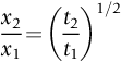
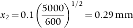
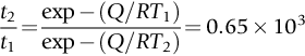
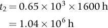
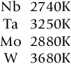
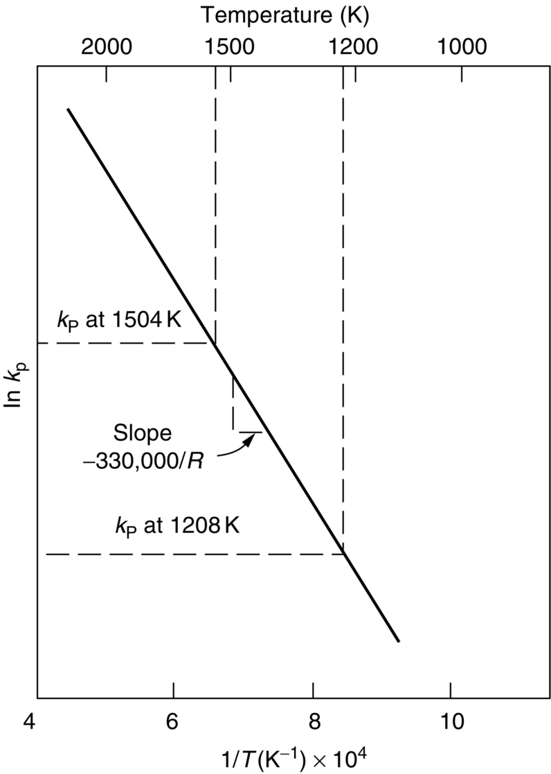
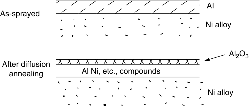
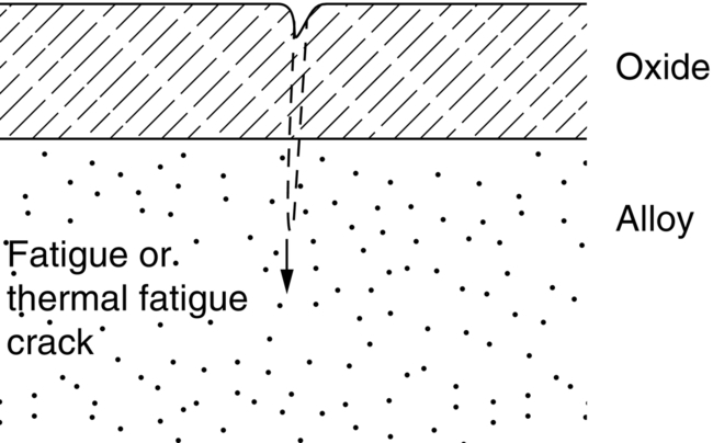
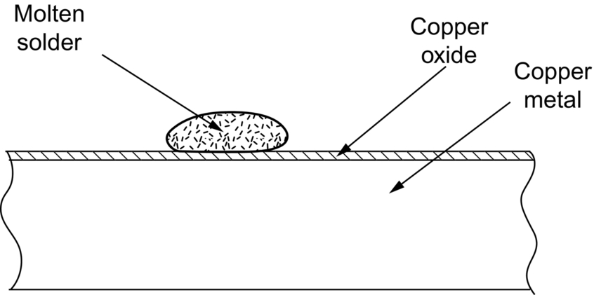
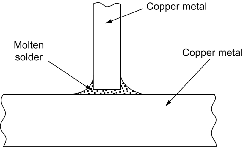
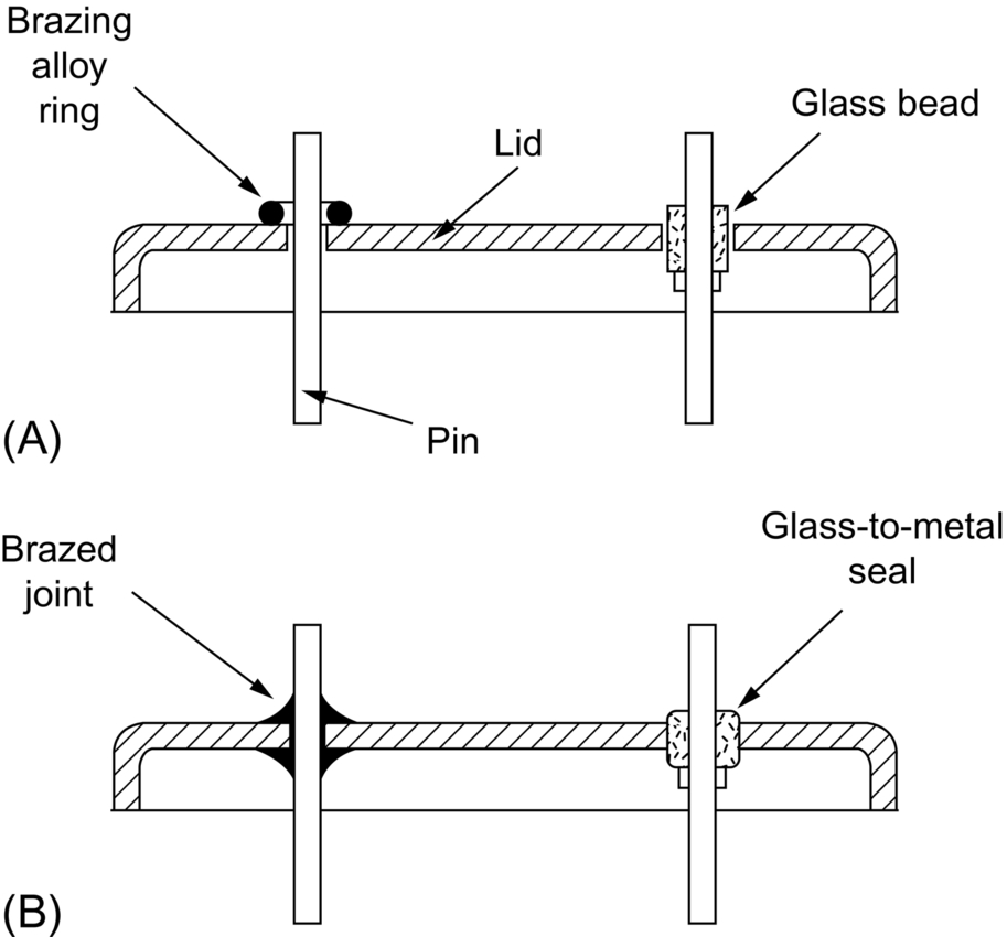
section epub:type=”chapter”> This chapter discusses case studies in dry oxidation. The chapter focuses on an important class of alloys designed to resist corrosion: the stainless steels. The chapter examines a complicated problem of protecting the most advanced gas turbine blades from gas attack. The basic principle applicable to both cases is to coat the steel or the blade with a stable ceramic—usually Cr2O3 or Al2O3. But the ways this is done differs widely. One might imagine that it is always a good thing to have a protective oxide film on a material; however, if one wishes to join materials by brazing or soldering, the protective oxide film can be a problem. It is this that makes stainless steel hard to braze and almost impossible to solder; even spot-welding and diffusion bonding become difficult. Protective films create poor electrical contacts—that is why aluminum is not more widely used as a conductor. And production of components by powder metallurgy, which involves compaction and sintering (diffusion bonding) of powdered material to the desired shape, is made difficult by protective surface films. In this chapter we look first at an important class of alloys designed to resist corrosion: the stainless steels. We then examine a more complicated problem: that of protecting the most advanced gas turbine blades from gas attack. The basic principle applicable to both cases is to coat the steel or the blade with a stable ceramic: usually Cr2O3 or Al2O3. But the ways this is done differ widely. Finally, we look at a process in which oxide films must not form on the surface—joining metals by soldering and brazing. Mild steel is an excellent structural material—cheap, easily formed, and strong. But at low temperatures it rusts, and at high temperatures, it oxidizes. There is a large demand, for high-temperature applications ranging from chemical reactors to superheater tubes, for oxidation-resistant steel. In response to this demand, a range of stainless irons and steels has been developed. When mild steel is exposed to hot air, it oxidizes quickly to form FeO (or higher oxides). But if one of the elements near the top of Table 25.1 with a large energy of oxidation is dissolved in the steel, then this element oxidizes preferentially (because it is more stable than FeO), forming a layer of its oxide on the surface. And if this oxide is a protective one, like Cr2O3, Al2O3, SiO2, or BeO, it stifles further growth, and protects the steel. A considerable quantity of this foreign element is needed to give adequate protection. The best is chromium, 18% of which gives a very protective oxide film: it cuts down the rate of attack at 900°C, for instance, by more than 100 times. Other elements, when dissolved in steel, cut down the rate of oxidation, too. Al2O3 and SiO2 both form in preference to FeO (refer to Table 25.1) and form protective films (refer to Table 25.2). Thus 5% Al dissolved in steel decreases the oxidation rate by 30 times, and 5% Si by 20 times. The same principle can be used to impart oxidation resistance to other metals. We shall discuss nickel and cobalt in the next Case Study—they can be alloyed in this way. So, too, can copper; although it will not dissolve enough chromium to give a good Cr2O3 film, it will dissolve enough aluminum, giving a range of stainless alloys called “aluminum bronzes.” Even silver can be prevented from tarnishing (reaction with sulfur) by alloying it with aluminum or silicon, giving protective Al2O3 or SiO2 surface films. Ceramics themselves are sometimes protected in this way. Silicon carbide, SiC, and silicon nitride, Si3N4, both have large negative energies of oxidation (meaning that they oxidize easily). But when they do, the silicon in them turns to SiO2 which quickly forms a protective skin and prevents further attack. Protection by alloying has one great advantage over protection by surface coating (like chromium plating or gold plating): it repairs itself when damaged. If the protective film is scored or abraded, fresh metal is exposed, and the chromium (or aluminum or silicon) it contains immediately oxidizes, healing the break in the film. As we saw in Chapter 24, the materials at present used for turbine blades consist chiefly of nickel, with various foreign elements added to get the creep properties right. With the advent of DS and SX blades, such alloys will normally operate around 950°C, which is close to 0.7TM for Ni (1208 K, 935°C). If we look at Table 25.2 we can see that at this temperature, nickel loses 0.1 mm of metal from its surface by oxidation in 600 h. The thickness of the metal between the outside of the blade and the integral cooling ports is about 1 mm, so in 600 h a blade would lose about 10% of its cross-section in service. This represents a serious loss in mechanical integrity and makes no allowance for statistical variations in oxidation rate—which can be quite large—or for preferential oxidation (at grain boundaries, for example) leading to pitting. Because of the large cost of replacing a set of blades, they are expected to last for more than 5000 h. Nickel oxidizes with parabolic kinetics (Equation (25.4)) so after a time t2, the loss in section x2 is given by substituting the data into: giving Obviously this sort of loss is not OK, but how do we stop it? As we saw in Chapter 24, the alloys used for turbine blades contain large amounts of chromium, dissolved in solid solution in the nickel matrix. If we look at Table 25.1, which gives the energies released when oxides are formed from materials, we see that the formation of Cr2O3 releases much more energy (701 kJ mol–1) than NiO (439 kJ mol–1). This means that Cr2O3 will form in preference to NiO on the surface of the alloy. Obviously, the more Cr there is in the alloy, the greater is the preference for Cr2O3. At the 20% level, enough Cr2O3 forms on the surface of the turbine blade to make the material act a bit as though it were chromium. Suppose for a moment that our material is chromium. Table 25.2 shows that Cr would lose 0.1 mm in 1600 h at 0.7TM. Of course, we have forgotten about one thing. 0.7TM for Cr is 1504 K (1231°C), whereas for Ni, it is 1208 K (935°C). We should probably consider how Cr2O3 would act as a barrier to oxidation at 1208 K rather than at 1504 K (Figure 26.1). The oxidation of Cr follows parabolic kinetics with an activation energy of 330 kJ mol–1. Then the ratio of the times required to remove 0.1 mm (from Equation 25.3) is Thus the time at 1208 K is Of course, there is only at most 20% Cr in the alloy, so the alloy behaves only partly as if it were protected by Cr2O3. Experimentally, we find that 20% Cr increases the time for a given metal loss by only about 10 times; that is, the time taken to lose 0.1 mm at blade working temperature becomes 600 × 10 h = 6000 h rather than 106 hours. Why this large difference? Whenever you consider an alloy rather than a pure material, the oxide layer—whatever its nature (NiO, Cr2O3, etc.)—has foreign elements contained in it, too. Some of these will greatly increase the diffusion coefficients or electrical conductivity of the layer, and make the rate of oxidation much more than it would be in the absence of foreign element contamination. One therefore has to be very careful in transferring data on film protectiveness from a pure material to an alloyed one, but the approach does give us an idea of what to expect. As in all oxidation work, however, experimental data on actual alloys are essential for design. This 0.1 mm loss in 6000 h from a 20% Cr alloy at 935°C, though better than pure nickel, is still not good enough. What is worse, we saw in Chapter 24 that, to improve the creep properties, the quantity of Cr has been reduced to 10%, and the resulting oxide film is even less protective. The obvious way out of this problem is to coat the blades with a protective layer (Figure 26.2). This is usually done by spraying molten droplets of aluminum on to the blade surface to form a layer, some microns thick. The blade is then heated in a furnace to allow the Al to diffuse into the surface of the Ni. During this process, some of the Al forms compounds such as AlNi, which are themselves good barriers to oxidation, while the rest becomes oxidized up to give Al2O3—which, as we can see from our oxidation-rate data—should be a very good barrier. An incidental benefit of the AlNi layer is its poor thermal conductivity—this helps insulate the metal of the cooled blade from the hot gases, and allows a slight extra increase in blade working temperature. Other coatings, though more difficult to apply, are even more attractive. It is possible to diffusion-bond a layer of Ni–Cr–Al alloy to the blade surface to give a ductile coating which forms a very protective film of oxide. And zirconium oxide (zirconia) is now used as a combined thermal barrier and oxidation protection coating on many hot end components. So far, we have been considering the advantage of an oxide layer in reducing the rate of oxidation. Oxide films, however, have some disadvantages. Because oxides are usually quite brittle at the temperatures encountered on a turbine blade surface, they can crack, especially when the temperature of the blade changes and differential thermal contraction and expansion stresses are set up between alloy and oxide. These can act as initiation sites for thermal fatigue cracks, and because oxide layers in nickel alloys are well bonded to the underlying alloy, the crack can spread into the alloy itself (Figure 26.3). The properties of the oxide film are therefore important in affecting the fatigue properties of the whole component. You may wonder why we did not mention the “refractory” metals Nb, Ta, Mo, and W in the chapter on turbine-blade materials. These metals have very high melting temperatures (see below) and should therefore have very good creep properties. But they all oxidize very rapidly indeed (refer to Table 25.2), and are useless without coatings. The problem with coated refractory metals is that if a break occurs in the coating (e.g., by thermal fatigue, erosion by dust particles, etc.), catastrophic oxidation of the underlying metal will take place, leading to rapid failure. The “unsafeness” of this situation is a major problem that has to be solved before we can use these otherwise excellent materials. The ceramics SiC and Si3N4 do not share this problem. They oxidize readily (refer to Table 25.1); but in doing so, a surface film of SiO2 forms which gives adequate protection up to 1300°C. And because the film forms by oxidation of the material itself, it is self-healing. We might think it is always a good thing to have a protective oxide film on the surface of a metal. But not always—if you want to join metals together by soldering, the protective film is a problem. For example, we often need to “soft” solder copper together—copper wires to copper tracks in PCBs, copper tubes and fittings together in plumbing installations. Traditional soft solder is an alloy of lead and tin, with a melting point between 184 and 327°C, depending on the percentages of Pb and Sn (there is pressure to replace the Pb in soft solders because of possible health risks). Even at room temperature, a copper surface has a very thin layer of oxide, and when the copper is heated to the melting temperature of the solder, the oxide grows. In order to solder copper parts together successfully, it is essential to have metal-to-metal contact between the solidified solder and the copper. The test is whether the solder—when molten—“wets” the copper surface. The solder will not wet the copper if there is oxide on the surface of the copper. Figure 26.4 shows a piece of copper, which was heated to the melting point of soft solder, and then had soft solder melted on top of it. You can see that the solder has “balled-up” on the copper surface. It has not spread out over the surface, because the solder has not “wetted” the copper. After cooling the copper back down to room temperature, you will find that it is possible to lever the ball of solder off the copper—there has not been metal-to-metal contact for the solder to stick to the copper. So the problem reduces to: “how do we get rid of the oxide layer on the copper before we apply the molten solder, and how do we make sure that the oxide cannot regrow while we are doing the soldering?”. Figure 26.5 shows the same test done on a copper component which was cleaned with abrasive paper, and then coated with flux. The flux is a soft paste of natural resin extracted from pine trees, which melts when the copper is heated up, and spreads out over the surface. The flux contains resin acids, which “dissolve” the oxide film at the soldering temperature, and it also acts as a barrier to oxygen, preventing the oxide from regrowing. You can see that the solder has wetted the copper surface. The solder is firmly attached to the copper, and the joint has considerable strength. The same issues arise when you try to soft solder other metals. Some, like copper alloys, mild steel, zinc-coated steel, and tin-coated steel, solder well—although different fluxes may be used to get the best results (for example zinc chloride solution—traditionally referred to as “tinner’s fluid”). But many other metals—such as aluminum, chromium, stainless steel (chromium again), magnesium, titanium, and beryllium—are difficult (or impossible) to soft solder in air, because their oxide films are so stable (mechanically and chemically). Techniques include using aggressive fluxes, and disrupting the oxide film mechanically while soldering, using a high-frequency transducer. For high-strength and/or high-temperature applications, metals are soldered with hard solders (often referred to as brazing). These typically melt in the range 610–950°C, depending on the alloy composition. Some are based on silver, and can contain exotic elements like palladium, in which case they are very expensive. At such high temperatures, oxidation is much faster. However copper, copper alloys, and carbon steel are easy to hard solder if aggressive fluxes, such as borax (sodium borate), are used. Of course, a great way to stop oxides forming is not to have any oxygen present at all. This principle is used in vacuum brazing. The parts to be brazed are cleaned mechanically and assembled, and then preformed rings or foils of hard solder are put in place. The assembly is placed in the vacuum furnace, the pressure is reduced to zero, and the furnace is heated up to the temperature needed to melt the brazing alloy. When the alloy melts, it wets the surfaces of the parent metal, and is sucked into the joints by capillary action. This produces a very fine and strong joint line, with none of the defects (such as trapped air or flux) that can be present in air-brazed joints. For “difficult” metals, hydrogen gas can be fed into the vacuum chamber to actively reduce any oxide (MO + H2 = M + H2O). Figure 26.6 shows an example of a component fabricated by vacuum brazing—the lid of a small pot containing an electronic device. This was press formed from thin Kovar sheet (a controlled expansion alloy with composition 54Fe29Ni17Co and melting point 1450°C). Kovar pins were brazed into holes in the lid as shown, using Pallabraze 950—an alloy with composition 54Ag25Pd21Cu and melting range 901–950°C. The furnace temperature was set at 1000°C. Figure 26.6(a) shows the assembly before heating, with the pin in position and a tiny preformed ring of Pallabraze around the pin. There is a small clearance between the pin and the hole (typically a few thou) so the brazing alloy can flow through the joint. When the furnace comes up to temperature, the ring melts, wets the oxide-free Kovar surfaces, and is sucked into the joint (Figure 26.6(b)). The diagrams also show the fabrication of a glass-to-metal seal between the lid and some of the other pins (designed to electrically insulate the lid from the pins). Small beads of low-expansion borosilicate glass were placed between the pins and the lid, and when the furnace came up to temperature the glass flowed and wetted the oxide-free metal surfaces. The brazing alloy was chosen so that both the brazing and the glass sealing could be done in one single operation.
Case Studies in Dry Oxidation
Publisher Summary
26.1 Introduction
26.2 Case Study 1: Making Stainless Alloys
26.3 Case Study 2: Protecting Turbine Blades
Influence of coatings on mechanical properties
Protecting future blade materials
26.4 Case study 3: Joining Metals by Soldering and Brazing
Examples
Answers