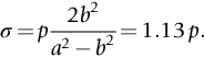
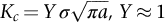
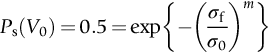
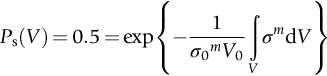
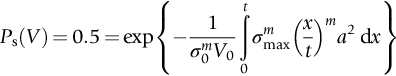
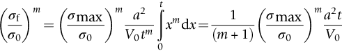
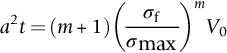
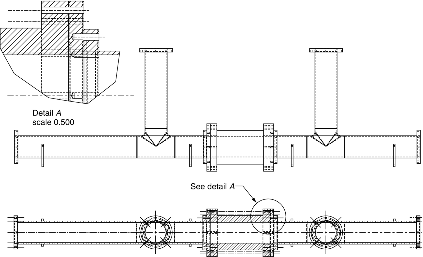
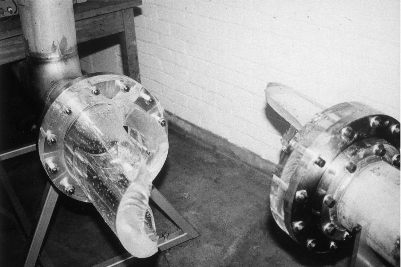
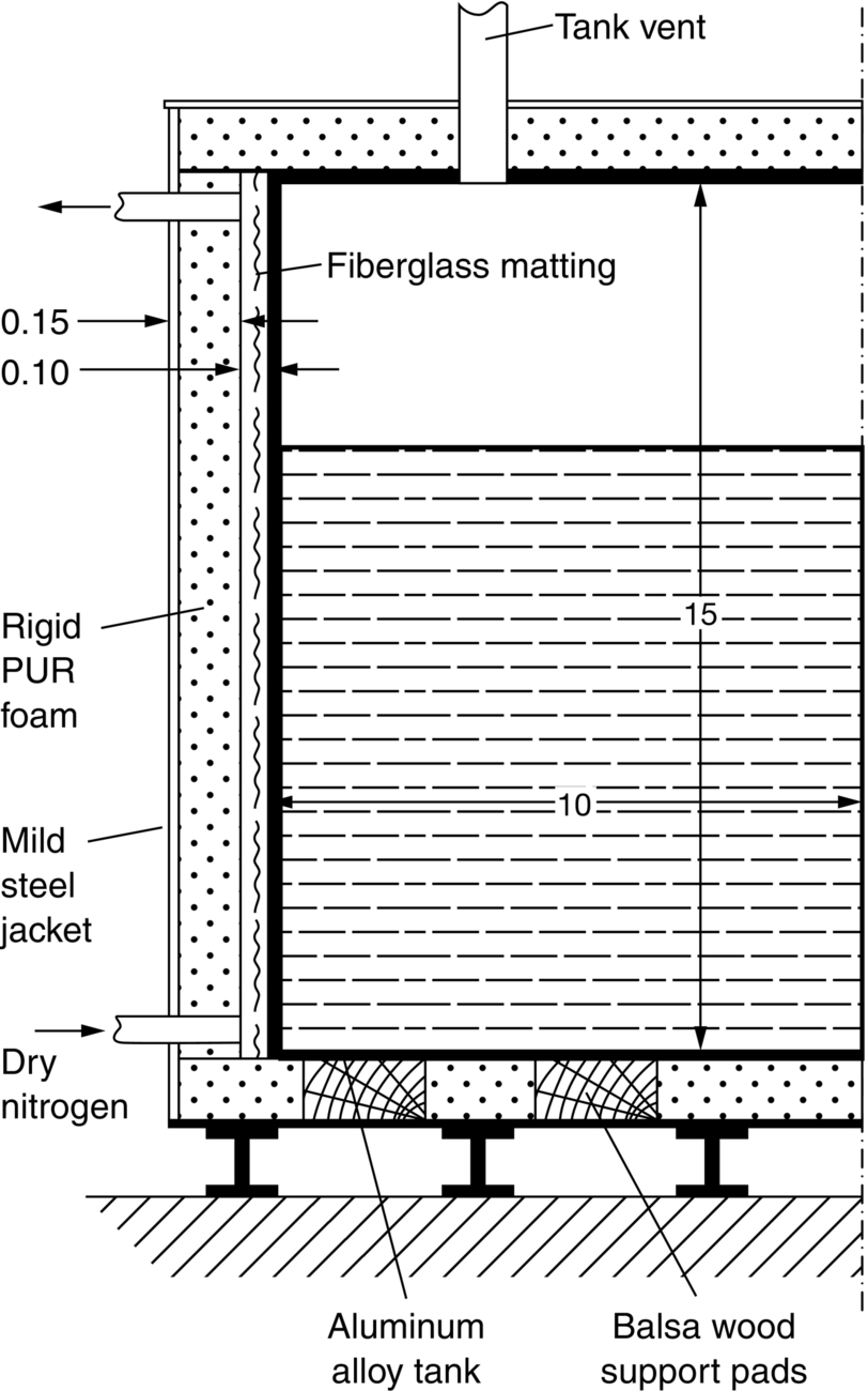
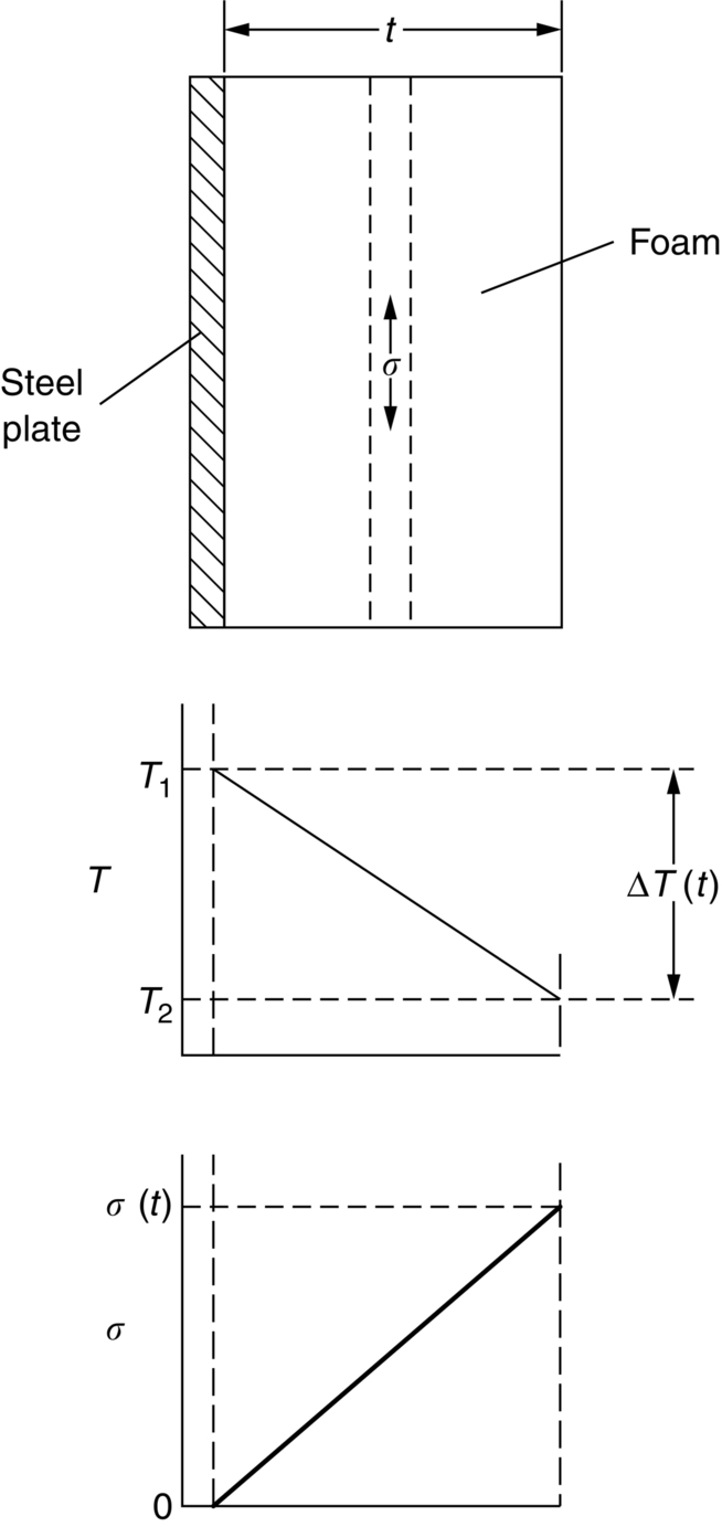
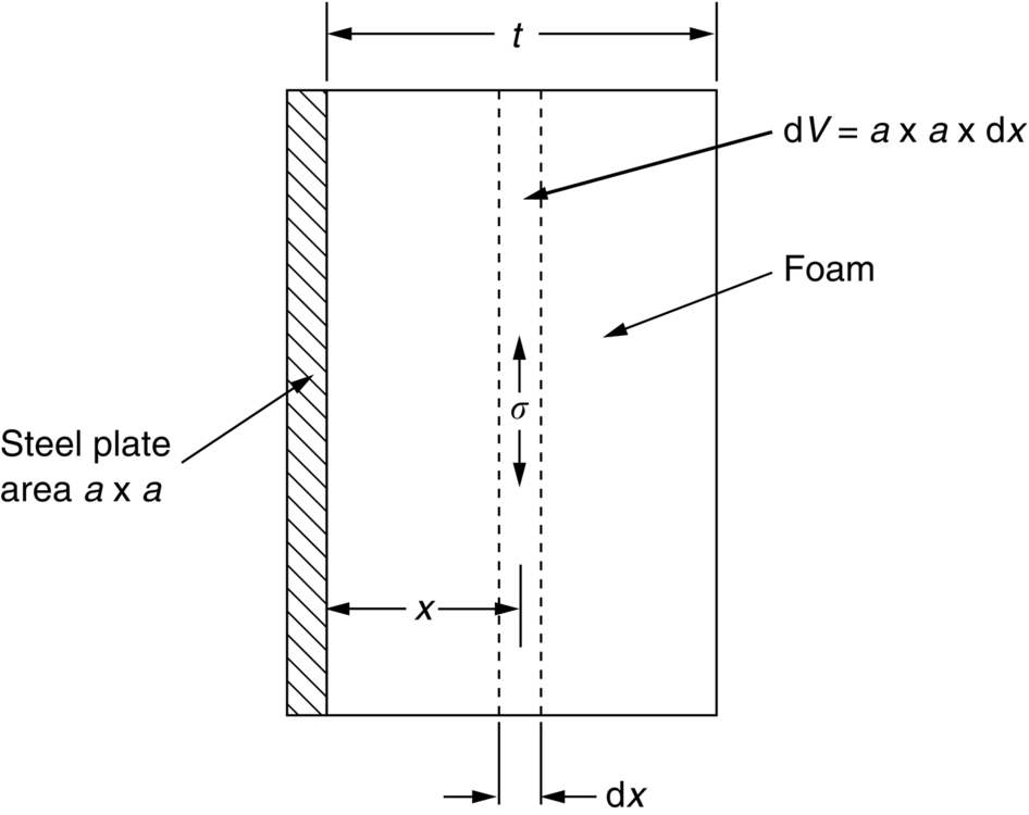
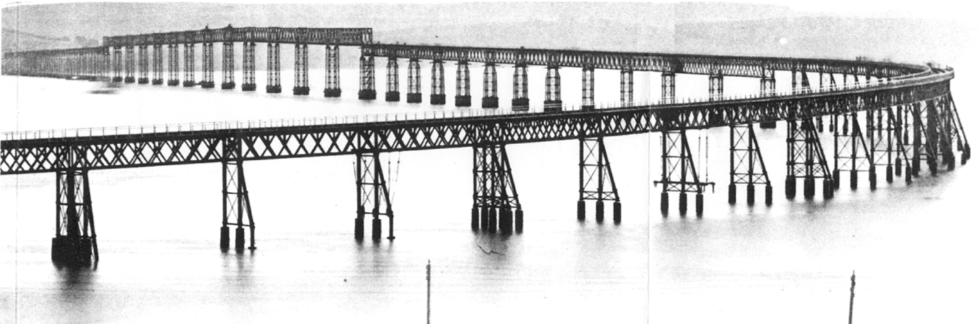
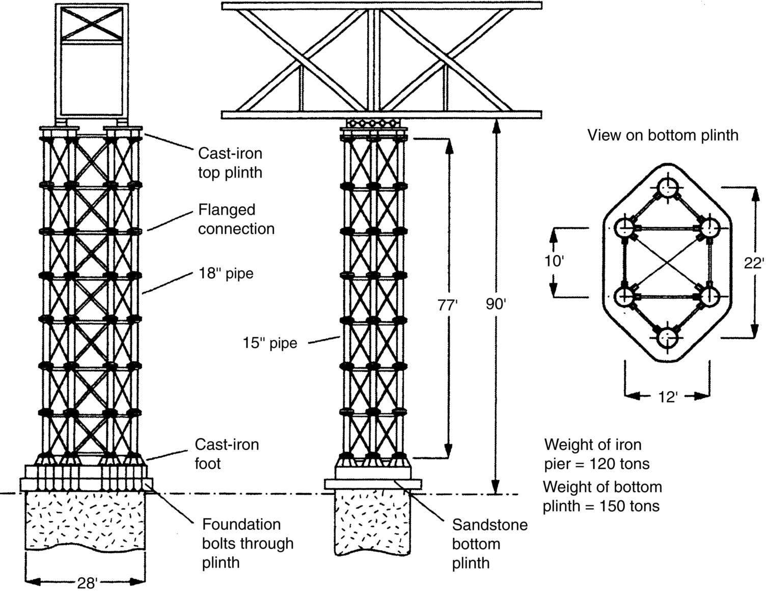
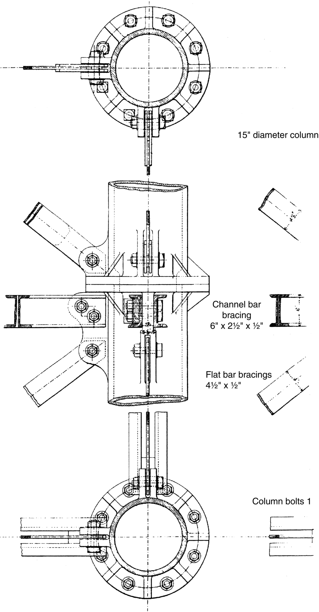
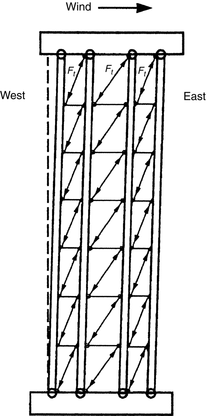
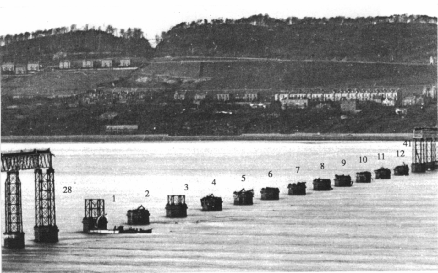
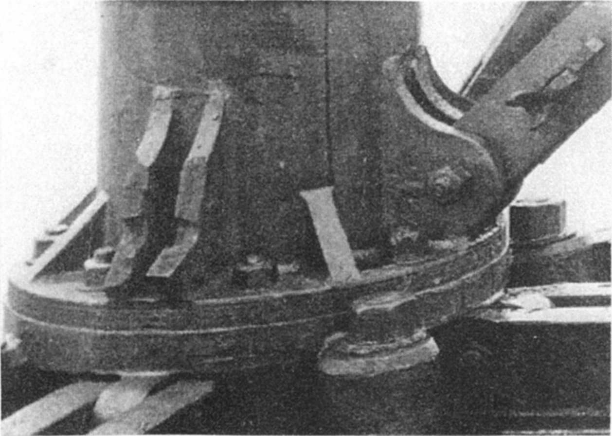
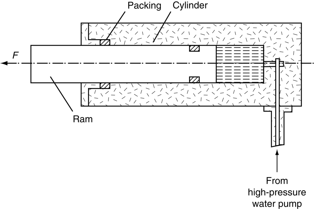
section epub:type=”chapter”> This chapter discusses three real situations where failure occurred because of the catastrophic growth of a crack by fast fracture: a steel ammonia tank that exploded because of weld cracks; a Perspex pressure window that exploded during hydrostatic testing, and a polyurethane foam jacket on a liquid methane tank that cracked during cooling. The chapter provides the details and analysis of the failure in each case. Additionally, the chapter illustrates through photographs and diagrams some working examples that show how the Tay Bridge was built and how it collapsed. In this chapter we look at three real situations where failure occurred because of the catastrophic growth of a crack by fast fracture: a steel ammonia tank which exploded because of weld cracks; a perspex pressure window which exploded during hydrostatic testing; and a polyurethane foam jacket on a liquid methane tank which cracked during cooling. Figure 17.1 shows part of a steel tank which came from a road tank vehicle. The tank consisted of a cylindrical shell about 6 m long. A hemispherical cap was welded to each end of the shell with a circumferential weld. The tank was used to transport liquid ammonia. In order to contain the liquid ammonia the pressure had to be equal to the saturation pressure (the pressure at which a mixture of liquid and vapor is in equilibrium). The saturation pressure increases rapidly with temperature: at 20°C the absolute pressure is 8.57 bar; at 50°C it is 20.33 bar. The gauge pressure at 50°C is 19.33 bar, or 1.9MN m-2. Because of this the tank had to function as a pressure vessel. The maximum operating pressure was 2.07MN m-2 gauge. This allowed the tank to be used safely to 50°C, above the maximum temperature expected in even a hot climate. While liquid was being unloaded from the tank a fast fracture occurred in one of the circumferential welds and the cap was blown off the end of the shell. In order to decant the liquid the space above the liquid had been pressurized with ammonia gas using a compressor. The normal operating pressure of the compressor was 1.83MN m-2; the maximum pressure (set by a safety valve) was 2.07MN m-2. One can imagine the effect on nearby people of this explosive discharge of a large volume of highly toxic vapor. The geometry of the failure is shown in Figure 17.2. The initial crack, 2.5 mm deep, had formed in the heat-affected zone between the shell and the circumferential weld. The defect went some way around the circumference of the vessel. The cracking was intergranular, and had occurred by a process called stress corrosion cracking (see Chapter 27). The final fast fracture occurred by transgranular cleavage (see Chapter 15). This indicates that the heat-affected zone must have had a very low fracture toughness. In this case study we predict the critical crack size for fast fracture using the fast fracture equation. The tank was made from high-strength low-alloy steel with a yield strength of 712 MN m-2 and a fracture toughness of 80 MN m-3/2. The heat from the welding process had altered the structure of the steel in the heat-affected zone to give a much greater yield strength (940 MN m-2) but a much lower fracture toughness (39 MN m-3/2). The longitudinal stress σ in the wall of a cylindrical pressure vessel containing gas at pressure p is given by provided that the wall is thin (t ≪ r) (see Example 7.5). p = 1.83 MN m-2, r = 1067 mm, and t = 7 mm, so σ = 140 MN m-2. The fast fracture equation is Figure 17.3 shows that Y = 1.92 for our crack. The critical stress for fast fracture is given by The critical stress is 64% greater than the longitudinal stress. However, the change in section from a cylinder to a sphere produces something akin to a stress concentration; when this is taken into account the failure is accurately predicted. This case study provides a good example of the consequences of having an inadequate fracture toughness. However, even if the heat-affected zone had a high toughness, the crack would have continued to grow through the wall of the tank by stress-corrosion cracking until fast fracture occurred. The critical crack size would have been greater, but failure would have occurred eventually. The only way of avoiding failures of this type is to prevent stress corrosion cracking in the first place. Figure 17.4 shows the general arrangement drawing for an experimental rig, which is designed for studying the propagation of buckling in externally pressurized tubes. A long open-ended tubular specimen is placed on the horizontal axis of the rig with the ends emerging through pressure seals. The rig is partially filled with water and the space above the water is filled with nitrogen. The nitrogen is pressurized until buckling propagates along the length of the specimen. The volumes of water and nitrogen in the rig can be adjusted to give stable buckling propagation. Halfway along the rig is a flanged perspex connector which allows the propagation of the buckle to be observed directly using a high-speed camera. Unfortunately, this perspex window exploded during the first hydrostatic test at a pressure of only one-half of the specified hydrostatic test pressure. Relevant design data for the perspex connector are given as follows. Figure 17.5 is a photograph of the perspex connector taken after the explosion. Detailed visual inspection of the fracture surface indicated that the fracture initiated as a hoop stress tensile failure in the cylindrical portion and subsequently propagated toward each flange. The hoop stress σ in the cylindrical portion can be calculated from the standard result for thick-walled tubes where p is the internal gauge pressure and r is the radius at which the stress is calculated. The hoop stress is a maximum at the bore of the tube, with r = b and The hoop stress is a minimum at the external surface of the tube, with r = a and We can see that the most probable site for failure initiation is the bore of the tube: the hoop stress here is calculated to be 10 MN m-2 at the failure pressure. This is only one-sixth of the minimum tensile strength. Using the fast fracture equation with a fracture toughness of 1 MN m-3/2 and a hoop stress of 10 MN m-2 gives a critical defect size a of 3.2 mm at the failure pressure. At the operating pressure the critical defect size would only be 1.5 mm. A defect of this size would be difficult to find under production conditions in such a large volume. In addition, it would be easy to introduce longitudinal scratches in the bore of the connector during routine handling and use. The most probable explanation for the failure is that a critical defect was present in the wall of the perspex connector. The connector was a standard item manufactured for flow visualization in pressurized systems. The designers had clearly used a stress-based rather than a fracture-mechanics based approach with entirely predictable consequences. Figure 17.6 is a schematic half-section through a tank used for storing liquid methane at atmospheric pressure. Because methane boils at –162°C, the tank is made from an aluminum alloy in order to avoid any risk of brittle failure. Even so, it is necessary to have a second line of defense should the tank spring a leak. This is achieved by placing the tank into a mild-steel jacket, and inserting a layer of thermal insulation into the space between the two. The jacket is thereby protected from the cooling effect of the methane, and the temperature of the steel is kept above the ductile-to-brittle transition temperature. But what happens if the tank does spring a leak? If the insulation is porous (e.g., fiberglass matting) then the liquid methane will flow through the insulation to the wall of the jacket and will boil off. As a result the jacket will cool down to –162°C and may fail by brittle fracture. To avoid this possibility the inner wall of the jacket is coated with a layer of closed-cell foam made from rigid polyurethane (PUR). The tank is then lowered into the jacket and the assembly gap is filled with fiberglass matting. The theory is that if the tank leaks, the flow of methane will be arrested by the closed-cell structure of the PUR and the jacket will be protected. This system has been used in ships designed for the bulk carriage of liquid methane. In such applications, the mild-steel jacket surrounding the tank is the hull of the ship itself. It is vital that the PUR provides effective containment. However, incidents have occurred where the PUR has cracked, compromising the integrity of the hull. In one reported instance, three brand-new bulk carriers had to be written off as a result of multiple cracking of the PUR foam layer. Under normal operating conditions, the temperature of the foam decreases linearly with distance through the layer, as shown in Figure 17.7. The foam wants to contract as it gets cold, but is prevented from doing so by the rigid steel wall of the jacket to which it is stuck. The temperature differential ΔT generates a biaxial tensile stress σ in the plane of the layer which is given by α, E, and υ are the coefficient of thermal expansion, Young’s modulus, and Poisson’s ratio of the foam. Figure 17.7 also shows the variation of stress with distance through the layer. The thermal stress is a maximum at the inner surface of the PUR layer. We saw in Chapter 6 that polymers behave as elastic-brittle solids provided they are colder than the glass transition temperature, TG. For PUR, TG ≈ 100°C, or 373 K. Presumably the foam failed by brittle cracking when the maximum thermal stress reached the fracture stress of the foam. To check this hypothesis we first list the relevant data for a typical PUR foam used in cryogenic applications. Referring to Figure 17.7, T1 ≈ 0°C, T2 ≈ –100°C, and ΔT(t) ≈ 100°C. For a temperature differential of this magnitude, σ ≈ 0.5 MN m-2. However, this value for the maximum stress is substantially less than the fracture stress of approximately 1.4 MN m-2 expected at –100°C. This means that, on a simple basis, the foam should not have fractured in service. In order to understand why the foam did in fact break it is necessary to analyze the problem using Weibull statistics. Tensile tests were carried out on foam samples at –100°C. The stressed volume of each sample V0 was ≈ 5 × 10⁻⁵ m3. The test data gave a median fracture strength (Ps = 0.5) of 1.4 MPa, and a Weibull modulus m of 8. The Weibull equation for the tensile tests is The Weibull equation for the foam layer is Referring to Figure 17.8, we set up a representative volume element “containing” a thermal stress Using these two results to substitute for σ and dV in Equation 17.2, we get Combining Equations (17.1) and (17.3) we get This gives and This means that there is a 50% chance that cracks will occur in the foam jacket at intervals of approximately 3.4 m. Considerable financial loss has resulted from the cracking of PUR foam in liquid methane insulation/containment systems. This has been caused by a combination of the very low fracture toughness of PUR foam at low temperature and the likelihood that the method of applying the foam will introduce defects exceeding the critical size for crack propagation. An elementary knowledge of Weibull Statistics would have suggested that the use of plain (unreinforced) PUR in the present situation was fundamentally unsound. The photographs and diagrams that follow show how the Tay Bridge was built, and how it collapsed. This single-track railway bridge was erected over the Firth of Tay, at Dundee, Scotland. It entered service in May 1878, but was blown over on 28 December 1879 by a storm force wind from the west, with a train that was carrying 75 people inside the high girders (the 13 central navigation spans of the bridge). The failure occurred because the sideways wind loading on the bridge girders and train put too much tension into the diagonal tie bars (wind braces), and broke the cast iron lugs to which they were attached. The bridge was subsequently demolished, and replaced with a massive double-track bridge. There is a great aerial view of the replacement bridge (casting reflections on the water), with the stumps of the old bridge alongside, on Google Earth at 56 26 20.00 N 2 59 18.70 W (see also http://taybridgedisaster.co.uk/index/index). Tests done after the disaster found that the cast iron lugs failed when the tension in the tie bars reached about 24 tons. The fracture area of a lug is about 20 sq. in. Tests on specimens taken from the cast-iron columns gave a tensile strength of 9 tons/sq. in. This indicates that the lug should have been able to carry a load of 180 tons applied by a tie bar. There is a factor of 7.5 times between this ultimate load of 180 tons and the actual measured breaking load of only 24 tons! Yet there was no indication that the cast iron was defective in any way. Pin and lug connections are important in the aerospace industry for attaching major fuselage components together (e.g., keel splice joints). They have been analyzed by linear elastic finite element stress analysis (FEA). Stress concentrations as high as 7.5 have been found from FEA. So it seems reasonable to think that the lugs broke because of local stress hot spots of the order of 9 tons/sq. in. next to the bolt holes. If the lugs had been made from a ductile material, like mild steel, they would not have fractured. The steel would have yielded at the stress concentration, and the local stress would have been truncated at the yield stress (which is much less than the tensile strength). However, in a brittle material, fracture intervenes before yield can take place, so the stress concentration predicted by FEA is still valid. We saw an example of this in Chapter 16, Section 16.4. The modulus of rupture test is used for brittle materials because specimens tend to break in the grips in a tensile testing machine. This is because the local contact stresses exceed the fracture strength—and because fracture occurs before yield, there can be no truncation of the local contact stresses. The conclusion is that ductile materials are much more forgiving than brittle materials—essentially for the same reason that ductile materials are much tougher than brittle materials (see Chapter 15). 51 29 15.62 N 0 01 15.38 W (Isle of Dogs, London, England) The cylinder of the ram (made from gray cast iron) split open under the internal water pressure. Estimate the tensile strength of the cast iron, given the following data. Water pressure inside cylinder = 83 MN m-2. External radius of cylinder = 279 mm. Internal radius of cylinder = 127 mm. Comment on the advisability of using gray cast iron for this application.
Case Studies in Fracture
Publisher Summary
17.1 Introduction
17.2 Case Study 1: Fast Fracture of an Ammonia Tank
Details of the failure
Material properties
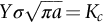
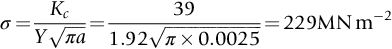
Calculation of critical stress for fast fracture
Conclusions
17.3 Case Study 2: Explosion of a Perspex Pressure Window during Hydrostatic Testing
Design data
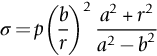
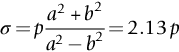
Failure analysis
Conclusions
17.4 Case Study 3: Cracking of a Foam Jacket on a Liquid Methane Tank
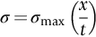
Thermal stresses in the foam
Conclusions
Worked Example
Examples
Which is the more dangerous crack, and why? [Hint: Make sure you use the correct values for Y.]
Answers
(a) 37.6 MN m–3/2, (b) 25.1 MN m–3/2. Crack (a) is more dangerous because it has the larger value of K, and also because it does not give leak before break.
 .
.
Fracture will commence at the bore of the cylinder when the hoop stress reaches the tensile strength of the material, i.e., the tensile strength = 126 MN m–2.
Gray cast iron is too brittle a material to use for making a pressure vessel. The fracture toughness is typically 10 MN m–3/2 (see Table 14.1). The critical defect size is given by Equation (14.4):  . From this, we get
 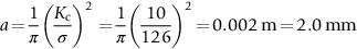 . This is far too small a critical defect size—a low-tech casting process cannot achieve this degree of control over casting defects.