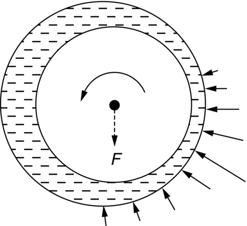
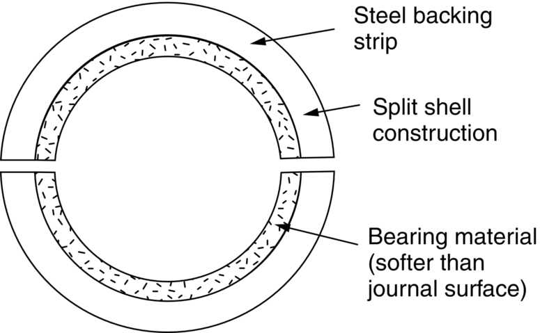
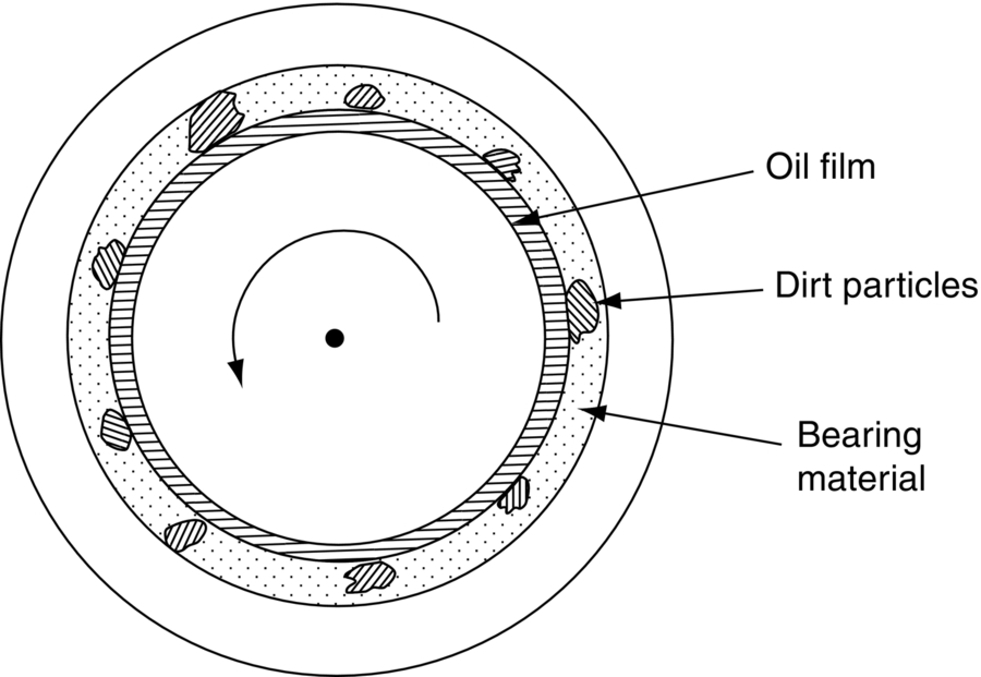
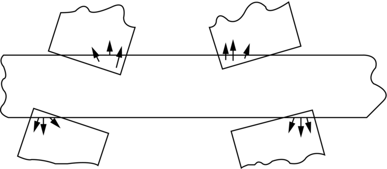
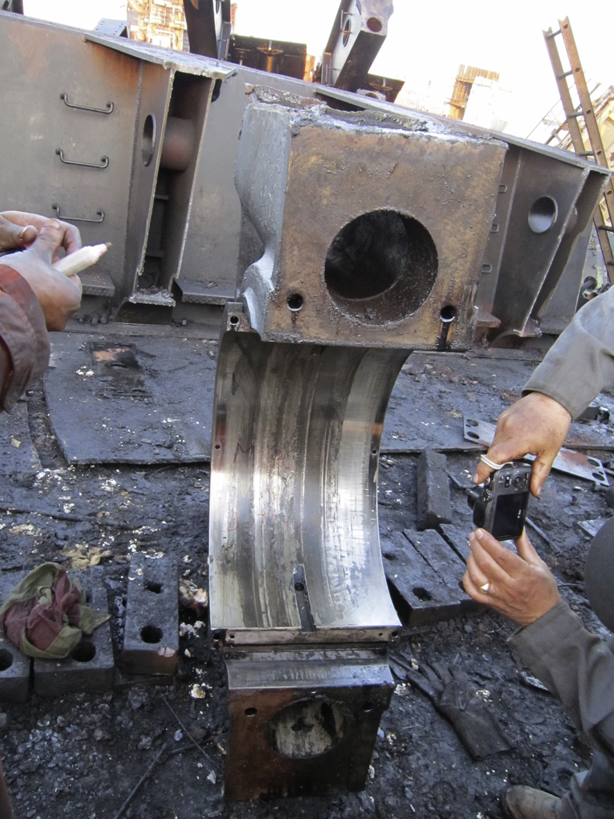
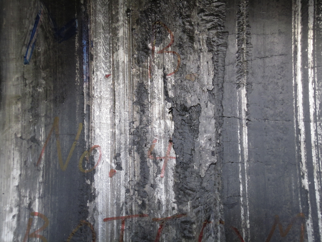
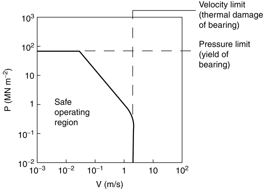
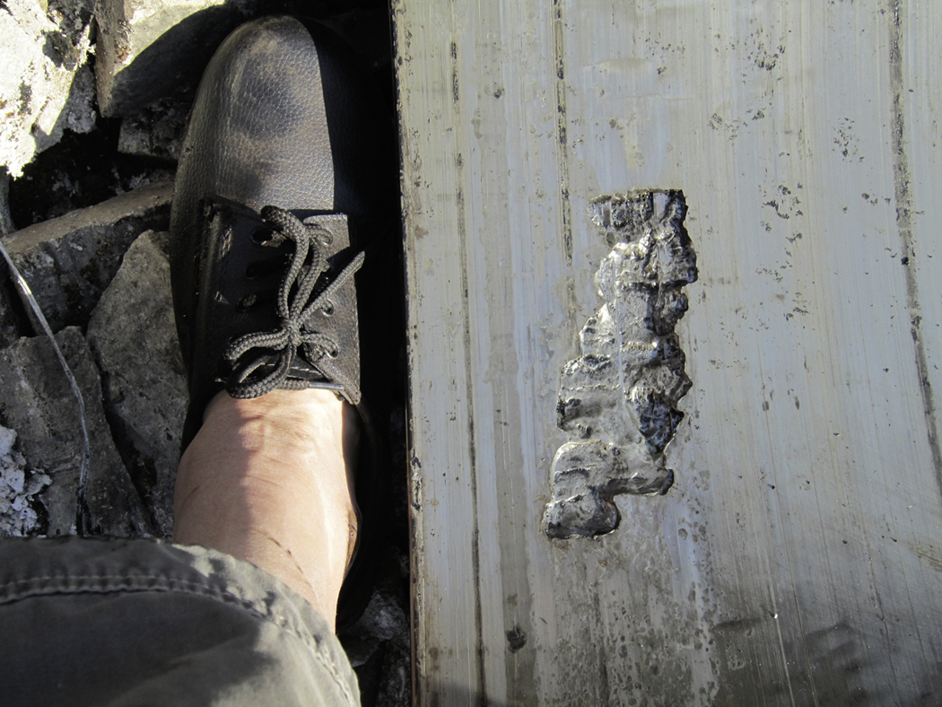
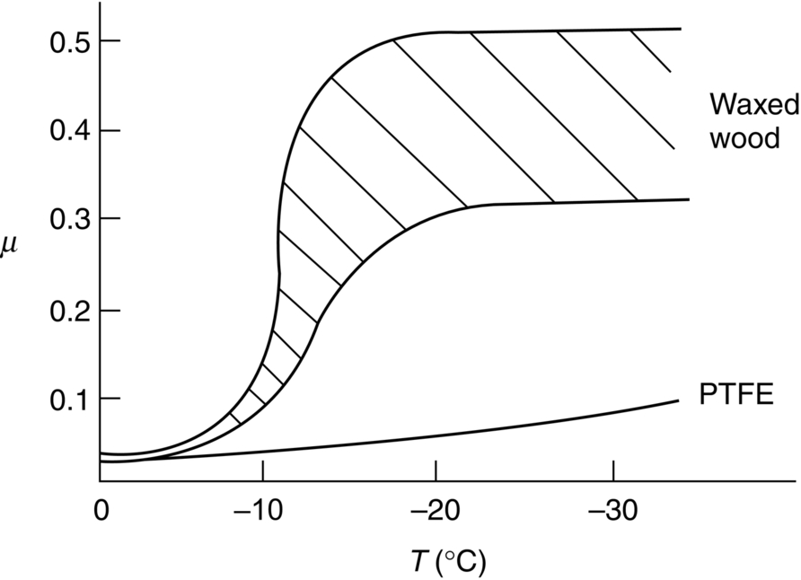
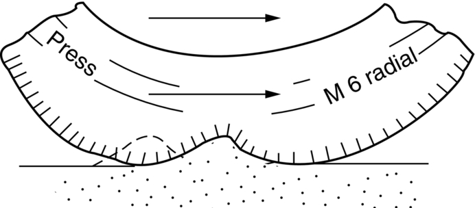
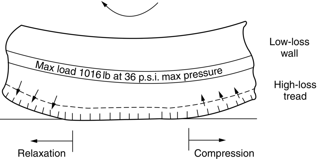
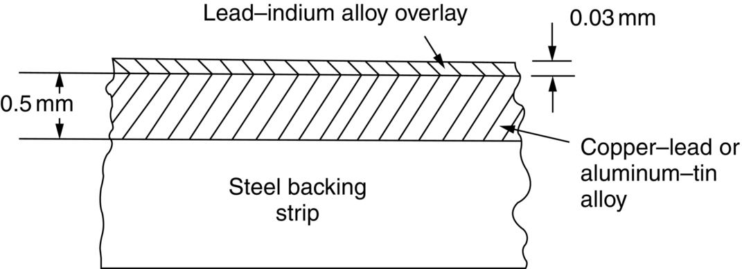
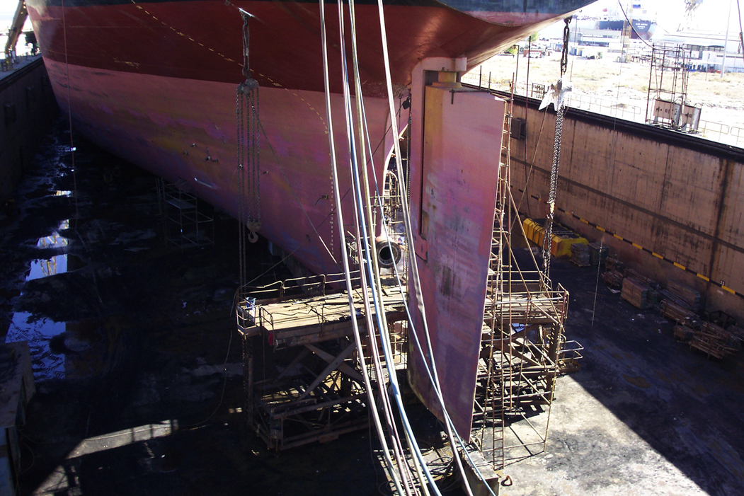
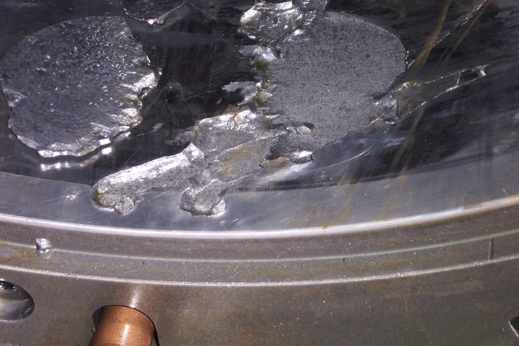
section epub:type=”chapter”> This chapter examines three different problems involving friction and wear. The first case study involves most of the factors that affect friction and wear: it is that of a round shaft or journal rotating in a cylindrical bearing. This type of journal bearing is common in all types of rotating or reciprocating machinery: the crankshaft bearings of an automobile are good examples. Furthermore, it includes several advantages of possessing a relatively soft bearing material. The second case study is quite different: it involves the frictional properties of ice in the design of skis and sledge runners. The third case study is an introduction to some of the frictional properties of polymers—that is, the selection of rubbers for anti-skid tires. In this chapter we examine three quite different problems involving friction and wear. The first involves most of the factors that appeared in Chapter 29: it is that of a round shaft or journal rotating in a cylindrical bearing. This type of journal bearing is common in all types of rotating or reciprocating machinery: the crankshaft bearings of an automobile are good examples. The second is quite different: it involves the frictional properties of ice in the design of skis and sledge runners. The third Case Study introduces us to some of the frictional properties of polymers: the selection of rubbers for anti-skid tires. In the proper functioning of a well-lubricated journal bearing, the frictional and wear properties of the materials are, surprisingly, irrelevant. This is because the mating surfaces never touch: they are kept apart by a thin pressurized film of oil formed under conditions of hydrodynamic lubrication.Figure 30.1 shows a cross section of a bearing operating hydrodynamically. The load on the journal pushes the shaft to one side of the bearing, so the working clearance is almost all concentrated on one side. Because oil is viscous, the revolving shaft drags oil around with it. The convergence of the oil stream toward the region of nearest approach of the mating surfaces causes an increase in the pressure of the oil film, and this pressure lifts the shaft away from the bearing surface. Pressures of 10 to 100 atmospheres are common under such conditions. Provided the oil is sufficiently viscous, the film at its thinnest region is still thick enough to cause complete separation of the mating surfaces. Under ideal hydrodynamic conditions there is no asperity contact and no wear. Sliding of the mating surfaces takes place by shear in the liquid oil itself, giving coefficients of friction in the range 0.001 to 0.005. Hydrodynamic lubrication is all very well when it functions properly. But when starting an engine up, or running slowly under high load, hydrodynamic lubrication is not effective, and we have to fall back on boundary lubrication (see Chapter 29). Under these conditions some contact and wear of the mating surfaces will occur (this is why car engines last less well when used for short runs rather than long ones). Crankshafts are difficult and expensive to replace when worn, whereas bearings can be designed to be cheap and easy to replace as shown in Figure 30.2. It is thus good practice to concentrate as much of the wear as possible on the bearing—and, as we showed in our section on adhesive wear in the previous chapter, this is done by having a bearing material that is softer than the journal—or a journal that is harder than the bearing material. Crankshaft journals can be “case-hardened” by special chemical and heat treatments (Chapter 29) to increase the surface hardness. (It is important not to harden the whole shaft because this will make it brittle and it might then break under shock loading.) Or bearing materials can be selected form the standard alloys which have been developed for this purpose (see Table 30.1). Table 30.1 There are several other advantages to having a relatively soft bearing material; these are described next. Real bearings contain dirt, such as small hard particles of silica. If the particles are thicker than the oil film, they will generate abrasive wear. But if the bearing surface is soft enough, these particles will be pushed into the surface, and removed from circulation (Figure 30.3). Slight misalignments of bearings can be self-correcting if plastic flow occurs easily in the bearing metal (Figure 30.4). But there is a compromise between load-carrying ability and conformability. If there is a breakdown in the oil supply, frictional heating will rapidly increase the temperature of the bearing, and this would normally lead to pronounced metal-to-metal contact, gross atomic bonding between journal and bearing, and seizure. A soft bearing material of low melting point will be able to shear in response to the applied forces, and may also melt locally. This helps to protect the journal from more severe damage, and also helps to avoid major component breakages which would result from the sudden locking-up of moving parts. Figures 30.5 and 30.6 show a typical example of overheating damage caused to the main crankshaft bearing of a marine diesel engine. The white metal bearing is badly scuffed, smeared, and oxidized, but there was no damage to the crankshaft journal. When designing a bearing for a particular application, it is useful to think in terms of the pressure-velocity (or “PV”) envelope inside which the bearing can function safely (Figure 30.7). We must ensure that the maximum pressure and sliding speed encountered in service will not make the material yield (see Table 30.1) or suffer heat damage. The PV envelope is not simply a property of the bearing material, but also the nature of the applied loading, the lubrication conditions, and the constructional details of the bearing. Although hydrodynamic lubrication should keep the surfaces apart, some frictional heating is generated even under ideal lubrication conditions. Much more heat can be generated if lubrication conditions revert to boundary lubrication or worse. A classic example can be found in the railway locomotive Mallard which holds the world speed record for steam railway locomotives of 125.9 mph (http://en.wikipedia.org/wiki/LNER_Class_A4_4468_Mallard). During the record-breaking run on 3 July 1938 the crank-pin bearing for the inside cylinder overheated. Steam was shut off immediately after the measured distance had been completed, and the locomotive had to stop at the nearest station. No doubt the combination of high sliding speed and the harsh, reciprocating loading took the bearing outside the limits of the PV envelope. Fluctuating loadings also occur, for example, in petrol and diesel engines, and are particularly pronounced in diesel engine crank-pin and crosshead bearings. Thus, in addition to the PV envelope, we also need to consider fatigue of the bearing material. This can lead to cracking in the bearing surface, and eventual detachment of pieces of bearing metal. Figure 30.8 shows a typical example of fatigue damage in a marine engine crank-pin bearing. As Table 30.1 shows, the fatigue strength depends strongly on the type of bearing material. Skis, both for people and for aircraft, used to be made of waxed wood. Down to about –10°C, the friction of waxed wood on snow is very low—μ is about 0.02—and if this were not so, planes equipped with skis could not take off from packed-snow runways, and the winter tourist traffic to Switzerland would drop sharply. Below –10°C, bad things start to happen (Figure 30.9): μ rises sharply to about 0.4. Polar explorers have observed this repeatedly. Wright, a member of the 1911–1913 Scott expedition, writes: “Below 0°F (–18°C) the friction (on the sledge runners) seemed to increase progressively as the temperature fell”; it caused the expedition considerable hardship. What determines the friction of skis on snow? Ice differs from most materials in that its melting point drops if you compress it. It is widely held that pressure from the skis causes the snow beneath to melt, but this is nonsense: the pressure of a large person distributed over a ski lowers the melting point of ice by about 0.0001°C and, even if the weight is carried by asperities that touch the ski over only 10–3 of its nominal area, the depression of the melting point is still only 0.1°C. Pressure melting, then, cannot account for the low friction shown in Figure 30.9. But as the person starts to descend the ski slope, work is done against the frictional forces, heat is generated at the sliding surface, and the “velocity limit” of Figure 30.7 is exceeded. The heat melts a layer of ice, producing a thin film of water, at points where asperities touch the ski: the person hydroplanes along on a layer of water generated by friction. The principle is exactly like that of the lead–bronze bearing, in which local hot-spots melt the lead, producing a lubricating film of liquid which lowers μ and saves the bearing. Below –10°C, heat is conducted away too quickly to allow this melting—and because their thermal conductivity is high, skis with exposed metal (aluminum or steel edges) are slower at low temperatures than those without. At these low temperatures, the mechanism of friction is the same as that of metals: ice asperities adhere to the ski and must be sheared when it slides. The value of μ (0.4) is close to that calculated from the shearing model in Chapter 29. This is a large value of the coefficient of friction—enough to make it very difficult for a plane to take off, and increasing by a factor of more than 10 the work required to pull a loaded sledge. What can be done to reduce it? This is a standard friction problem. A glance at Figure 29.5 shows that, when polymers slide on metals and ceramics, μ can be as low as 0.04. Among the polymers with the lowest coefficients are PTFE (“Teflon”) and polyethylene. By coating the ski or sledge runners with these materials, the coefficient of friction stays low, even when the temperature is so low that frictional heating is unable to produce a boundary layer of water. Aircraft and sports skis now have polyethylene or Teflon undersurfaces; the Olympic Committee has banned their use on bob-sleds, which already, some think, go fast enough. So far we have talked of ways of reducing friction. But for many applications—brake pads, clutch linings, climbing boots, and above all, car tires—we want as much friction as we can get. The frictional behavior of rubber is quite different from that of metals. In Chapter 29 we showed that when metallic surfaces were pressed together, the bulk of the deformation at the points of contact was plastic; and that the friction between the surfaces arose from the forces needed to shear the junctions at the areas of contact. But rubber deforms elastically up to very large strains. When we bring rubber into contact with a surface, therefore, the deformation at the contact points is elastic. These elastic forces still squeeze the atoms together at the areas of contact, of course; adhesion will still take place there, and shearing will still be necessary if the surfaces are to slide. This is why car tires grip well in dry conditions. In wet conditions, the situation is different; a thin lubricating film of water and mud forms between rubber and road, and this will shear at a stress a good deal lower than previously, with dangerous consequences. Under these circumstances, another mechanism of friction operates to help prevent a skid. It is illustrated in Figure 30.10. All roads have a fairly rough surface. The high spots push into the tire, causing a considerable local elastic deformation. As the tire skids, it slips forward over the rough spots. The region of rubber that was elastically deformed by the rough spot now relaxes, while the rubber just behind this region becomes compressed as it reaches the rough spot. Now, all rubbers exhibit some anelasticity; the stress–strain curve looks like Figure 30.11. As the rubber is compressed, work is done on it equal to the area under the upper curve; but if the stress is removed we do not get all this work back. Part of it is dissipated as heat—the part shown as the shaded area between the loading and the unloading curve. So to make the tire slide on a rough road we have to do work, even when the tire is well lubricated, and if we have to do work, there is friction. Special rubbers have been developed for high-loss characteristics (called “high-loss” or “high-hysteresis” rubbers) and these have excellent skid resistance even in wet conditions. There is one obvious drawback of high-hysteresis rubber. In normal rolling operation, considerable elastic deformations still take place in the tire wall, and high-loss tires will consume fuel and generate considerable heat. The way out is to use a low-loss tire covered with a high-loss tread—another example of design using composite materials (Figure 30.12). With reference to Example 12.2, modify the analysis for the situation where there is no friction between the bar and the upper anvil, but there is sticking friction between the bar and the lower anvil. This models the situation in the bearing (bar = soft bearing material, upper anvil = oil film, lower anvil = steel backing strip). Hence show that Verify that the general formula now becomes For a bearing layer 0.5 mm thick, and a bearing shell 40 mm wide, find the ratio between the yield load of the bearing layer, and the yield load of an unconstrained sample of bearing material. At the start of the clip, the driving wheels of the loco can be seen slipping on the rail because it is damp from the overnight dew. Shortly afterward, the two “sand boys” can be seen dropping sand on to the rails just in front of the loco to help the wheels get a grip. Why was the loco slipping in the first place, and why should sand stop the loco slipping?
Case Studies in Friction and Wear
Publisher Summary
30.1 Introduction
30.2 Case Study 1: Design of Journal Bearings
Alloy
σy (MN m–2)
Fatigue Strength
White metal (lead based)
Pb – 10% Sb, 6% Sn
White metal (tin based)
Sn – 8% Sb, 4% Cu
Aluminum based
Al – 40% Sn
Al – 6% Sn, 1% Ni
Al – 11% Si, 1% Cu
Copper based
Cu – 30% Pb
Cu – 20% Pb, 5% Sn (leaded bronze)
Cu – 10% Sn, 1% P (phosphor bronze)
30
60
40
50
90
60
125
230
Low
Low
Low
Medium
Good
Medium
Good
Good
Embeddability
Conformability
Preventing seizure
30.3 Case Study 2: Materials for Skis and Sledge Runners
30.4 Case Study 3: High-Friction Rubber

Examples
Answers
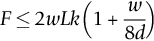
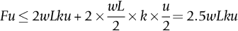
This result was derived for the case of w/d = 2 (see Example 12.2). Inserting this value of w/d into the general formula gives F ≤ 2.5wLk.
For d = 0.5 mm and w = 40 mm, F ≤ 22wLk. The yield load of the unconstrained sample is obtained by setting w/8d = 0. The ratio of the constrained to unconstrained yield loads = 11. This is a huge gain in the effective strength of the bearing material.