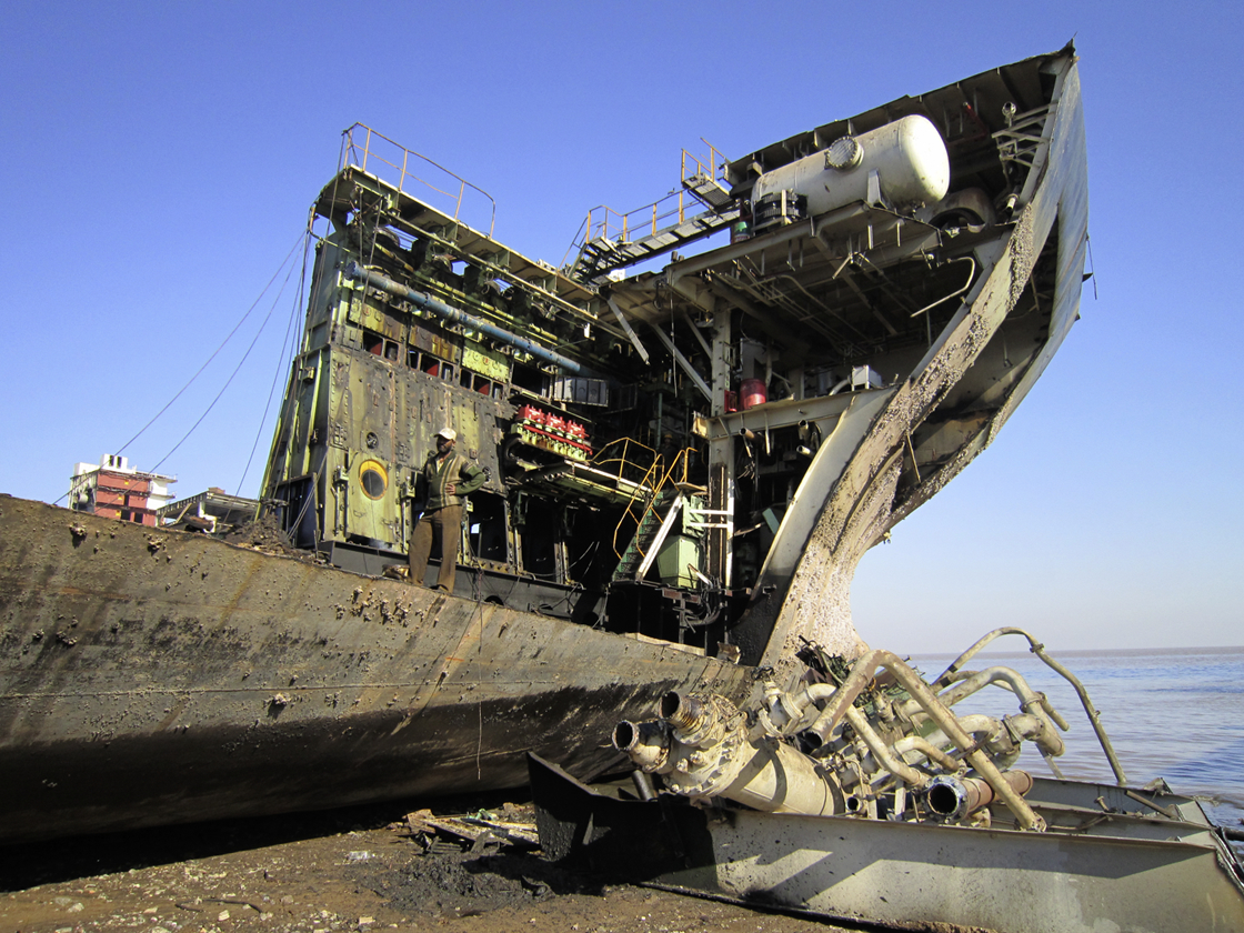
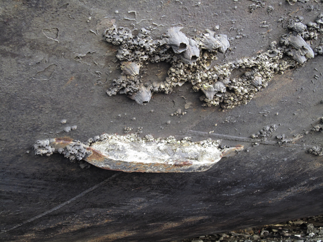
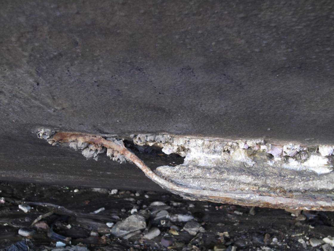
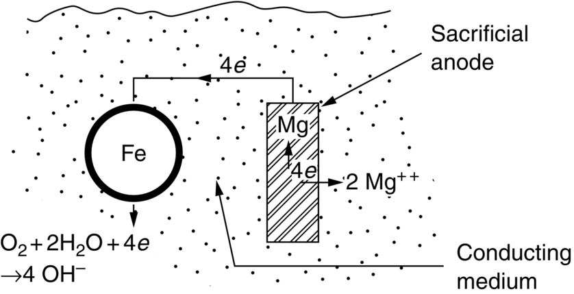
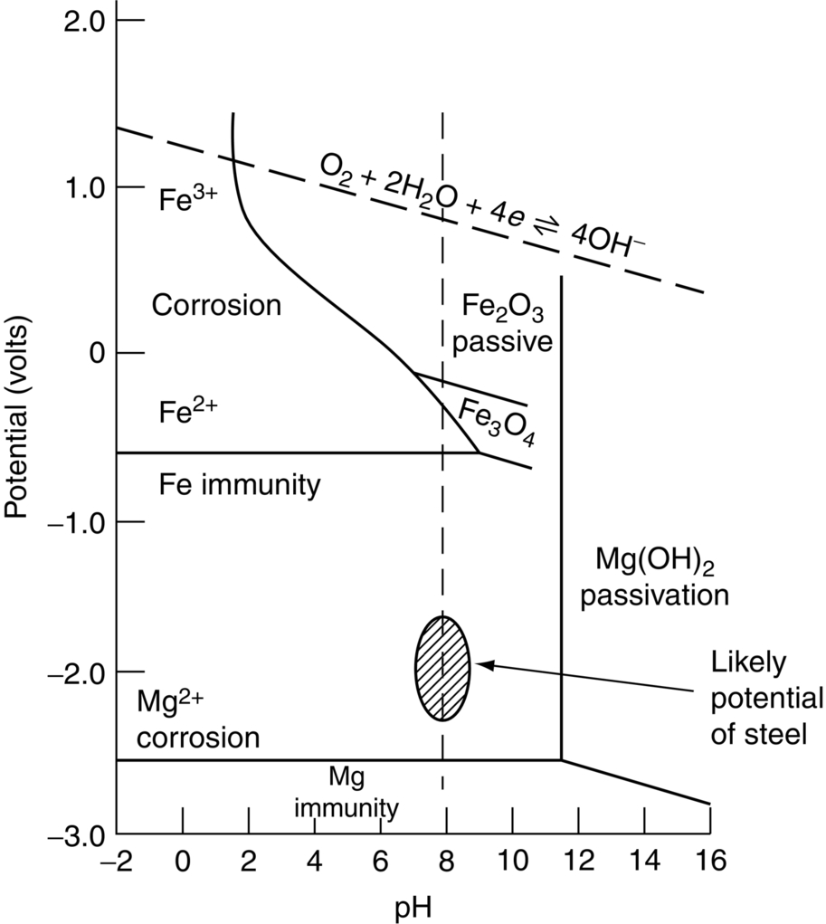
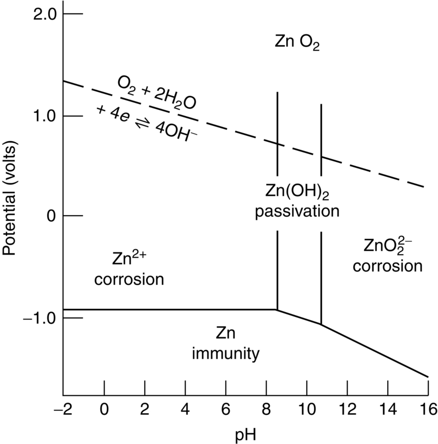
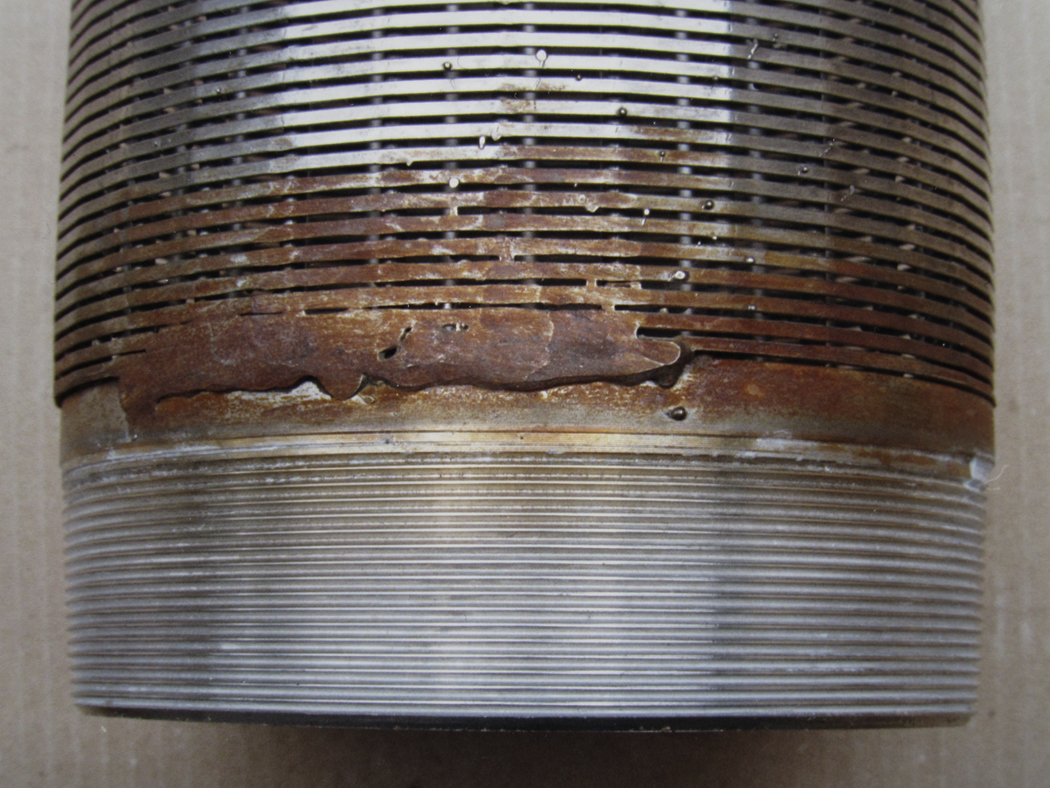
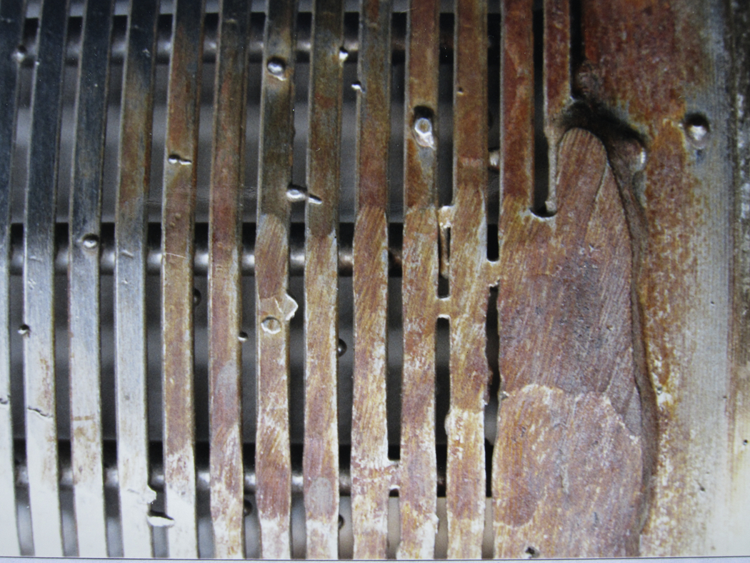
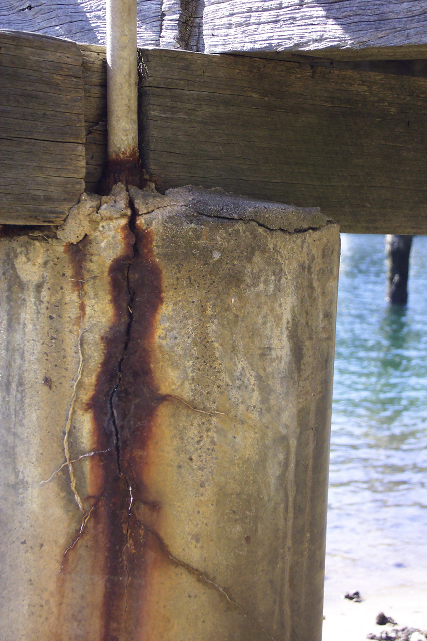
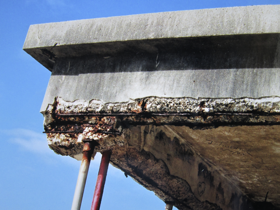
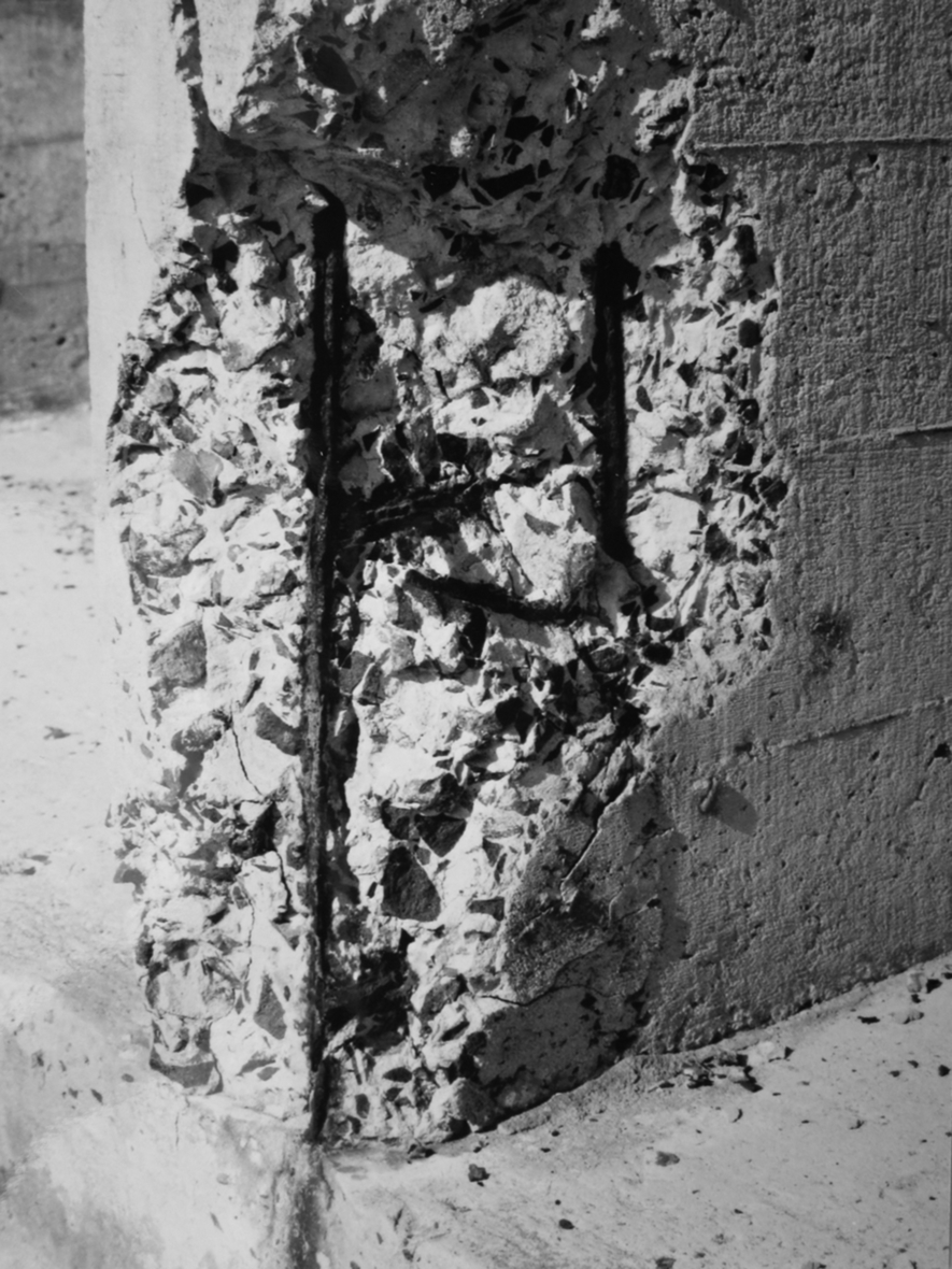
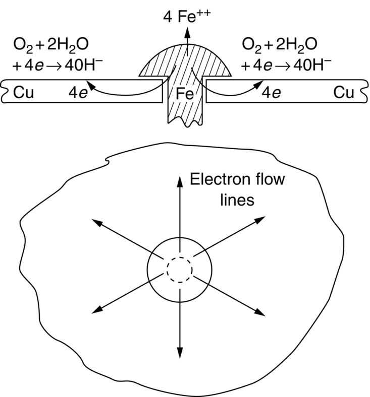
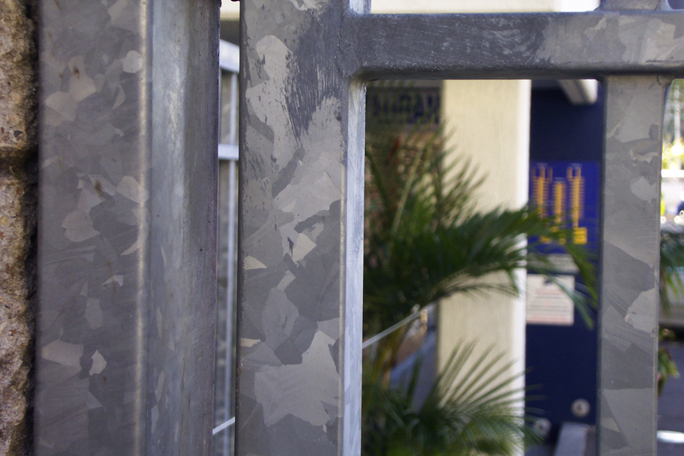
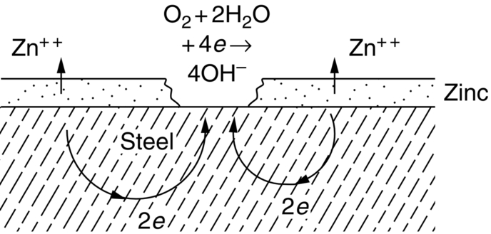
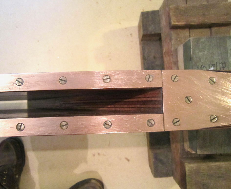
section epub:type=”chapter”> This chapter discusses three cases of wet corrosion. The first case is that of protecting hulls of ships from corrosion. This case shows a large cargo ship in the final stages of being scrapped. Because the hull is sitting on the beach, it dries out at low tide, exposing details that would not normally be visible. It shows a magnesium sacrificial anode bolted to the steel hull just above the keel as another example. The second case is about rusting of a stainless steel water filter. The final case in this chapter is about corrosion in reinforced concrete. This chapter concludes with a note on small anodes and large cathodes. Figure 28.1 shows a large cargo ship in the final stages of being scrapped. Because the hull is sitting on the beach, it dries out at low tide, exposing details that would not normally be visible. Figures 28.2 and 28.3 show a magnesium sacrificial anode bolted to the steel hull just above the keel—similar anodes are regularly spaced along the length and breadth of the vessel below the waterline. But what are these for? Figure 28.4 shows how the sacrificial anode works. Table 27.1 shows that the standard electrode potentials for iron and magnesium are –0.44 V and –2.36 V. The SEP for magnesium is therefore 1.9 V less than that for iron. If these two metals are wired together in a conducting medium (e.g., seawater), the magnesium becomes the anode and corrodes. The iron becomes the cathode, where the oxygen reduction reaction takes place, and does not corrode. Although this difference in SEP suggests that the magnesium should protect the steel, we still need to check that no stable protective film will form on the surface of the magnesium, because this would prevent it from corroding. Figure 28.5 shows the Pourbaix diagram for magnesium (with part of the Pourbaix diagram for iron superposed on it). The pH of seawater is about 8, so magnesium does not form a protective oxide film in seawater. Figure 28.5 also shows why the steel is protected. The potential of the steel is pulled down by the corrosion of the magnesium so that it ends up well within the region of Fe immunity on the Pourbaix diagram for iron. Because this turns the steel into the cathode, protecting it using sacrificial anodes is also called cathodic protection (referred to in the trade as “CP”). Figure 28.3 shows the anode being eaten away by corrosion. In order to minimize the loss of anode metal, it is important to protect the steel by painting it. However, paint does not provide complete protection—it gets scratched and abraded in service (for example, when removing marine organisms like the barnacles shown in Figure 28.2), and it is also attacked by long term exposure to seawater. The role of CP is to protect the steel from corrosion where the paint breaks down. Zinc could also be used to protect the steel. Table 27.1 shows that the standard electrode potentials for iron and zinc are –0.44 V and –0.76 V. The difference of 0.3 V is still enough to make the iron the cathode, because zinc does not form a stable oxide film below a pH of 8.5 (see Figure 28.6). Aluminum (SEP = –1.66) is less straightforward. As Figure 27.10 shows, aluminum forms a stable protective film in the pH range 4 to 8.5, so in theory it should not corrode in seawater (pH = 8). However the high concentration of chloride ions in seawater attacks the film, allowing the anode to corrode. Alloying the aluminum with 5% zinc also helps it to corrode. Titanium (SEP = –1.63) does not work, because the surface film stops it corroding. Figure 28.7 and 28.8 show part of a water filter. The filter consisted of a perforated tube with a diameter of 200 mm. The end of the tube was welded to a short screwed section and this was used to couple the filter to a length of ordinary nonperforated pipe. The filter was intended for use in a water-supply network on an irrigation project. The components were made from an austenitic stainless steel of type AISI 304. The perforated tube was made by assembling a tubular cage of steel rods and welding the end of each rod to the screwed coupling. A helix of steel wire was then wound around the outside of the cage to complete the perforated wall. The wire was fixed to the support rods by electrical-resistance spot welding. For some reason the connection between the end of the helix and the coupling was not satisfactory. To correct this an extra weld had been made on the outside of the coupling. Finally the weld and the adjoining helix were leveled by grinding. The filters were transported to their destination by sea. When they were unloaded it was noticed that some of the repair welds had corroded. A closer inspection revealed that corrosion had occurred not just on the weld bead itself but also on the parts of the helix that had been ground flat. The surface was not pitted, but was covered with a thin uniform deposit of red rust. The standard range of austenitic stainless steels is prone to a number of corrosion problems—the rather vague description “stainless” cannot necessarily be taken to mean “immune to corrosion.” The iron in stainless steel wants to react with the environment and the metal depends for its corrosion resistance on the very thin protective film of chromium oxide. If the passive film breaks down for any reason then stainless steel can corrode very rapidly indeed. When the filters were unloaded from their containers they were found to be running with condensation. The film of condensed water would have been saturated with air and would probably have contained a significant concentration of chloride ions picked up from the salty atmosphere. The solution should then have been an ideal medium for corrosion, with an ample supply of oxygen and a reasonable electrical conductivity. Chloride ions are also very effective at breaking down the protective films that form on most metals. In view of this it is not surprising that the weak areas were identified in the surface film on the filters. When a fresh, dry surface of stainless steel is exposed to the oxygen in the atmosphere the passive oxide film rapidly forms of its own accord. For critical applications (e.g., water pipes in the nuclear industry) the film can even be thickened artificially by treating the surface with an oxidizing agent such as nitric acid. However, problems can arise when stainless steel is welded. Because the surface of the weld bead is exposed to the atmosphere at high temperature it oxidizes. A layer of black oxide scale forms on the surface of the weld bead. Unfortunately this high-temperature oxide protects the metal much less well than the normal passive film. The problem can be solved by removing the oxide with a pickling solution of nitric and hydrofluoric acids. This produces a fresh clean surface which is rinsed and allowed to passivate naturally in air. What seems less obvious is why the outside of the filter rusted even though the oxide scale had been ground off. The answer is that the rough, cold-worked surface produced by grinding is more liable to corrode than a smooth stress-free surface. Indeed, stainless steel components for critical applications are often “cleaned” by electropolishing. This dissolves away the cold-worked layer, producing a surface that is smooth, clean, and stress-free and which forms an optimum base for the passive film. Electropolished stainless steel is much in demand in the medical, pharmaceutical, and food-handling industries where freedom from contamination is essential. AISI 304 is the most common and basic stainless steel—it contains to 18 to 20% Cr (and 8–10.5% Ni to make it f.c.c.). Its resistance to corrosion (especially pitting) can be improved a lot by adding molybdenum, which helps to stabilize the passive film. The most common stainless steel containing Mo is AISI 316, which has 2 to 3% Mo, as well as 16 to 18% Cr (and 10–14% Ni). More recently the super austenitics have been developed, such as 254 SMO and AL-6XN. These contain even more Mo (6%), Cr (20%), and Ni (20%), plus about 0.2% nitrogen. The N is absorbed as an interstitial solid solution—it is 16 times as effective as Cr in resisting pitting (and, incidentally, raises the yield strength by 25% because it pins dislocations). These alloys are also highly resistant to stress corrosion cracking. Finally, the new super duplex steels such as SAF 2507 have more Cr (25%), and less Mo (4%) and Ni (7%) than the super austenitics. The low Ni content gives them a mixed (or duplex) f.c.c./b.c.c. structure, which has a yield strength twice that of 304 or 316. Because Ni is expensive, they are cheaper than the super austenitics yet are just as resistant to pitting and stress corrosion cracking. Such are the complications of developing alloys to resist corrosion! Figure 28.9 shows a reinforced concrete pile at the Inkerman Street Wharf in Sydney Harbour. The steel reinforcement has rusted and caused cracking and splitting of the surrounding concrete (the dark stains are rust deposits). Why has this happened? When steel rusts, the volume of rust produced is greater than the volume of steel that is lost. This is partly because the density of iron oxide is less than that of steel (5.26 Mg m–3 for Fe2O3 compared to 7.8 Mg m–3 for steel). But because the rust deposits are hydrated (FeO·H2O) and full of voids, their density is usually much less again—as a rough guide, if the surface of the steel corrodes back by 1 mm, it will produce a layer of rust scale 5 to 10 mm thick. So if the steel reinforcement bars inside the concrete rust, they “expand,” and crack open the surrounding concrete. This type of attack is most likely to occur when there is not enough thickness of concrete over the steelwork (“cover”) to protect it from the environment, or when there is a lot of chloride ion around. This can come from an incorrect cement mix (too much calcium chloride). Or it can come from exposure to salt–immersion in seawater, exposure to a marine atmosphere, or de-icing salt on highways. The pile at the Inkerman Street Wharf cracked because of a combination of insufficient cover and a very salty environment. Figures 28.10 and 28.11 show more examples, from a structure on South Head, Sydney—a place where there is a lot of salt-water spray in the air. Chunks of concrete have come away from the structure, exposing the steel reinforcement bars (a phenomenon known as spalling). The concrete in these examples is beyond repair, but there are many cases where repairs are technically possible and cost-effective—for example, highway bridges that have suffered superficial spalling of concrete where the underlying reinforcement is not too badly corroded. The spalled areas are repaired using cement mortar, and a cathodic protection system is installed to prevent further corrosion of the steelwork. Holes are drilled into the surface of the concrete at regular intervals, and plugs of zinc are cemented into them. The zinc anodes are electrically connected to the steelwork by copper wires. A good example is given at http://www.vector-corrosion.com/2009/09/ten-year-results-of-galvanic-sacrificial-anodes-in-steel-reinforced-concrete/, which describes cement repairs made to a highway bridge in the United Kingdom in 1999. When some zinc anodes were removed for examination in 2009, it was found that only 35% of the zinc had been used up in protecting the steelwork, indicating that the repairs should have a life of at least 25 years before the anodes need renewing. Figure 28.12 shows a classic corrosion design error—fixing a sheet copper roof in place using ordinary steel screws. The SEPs for copper and iron are +0.34 and –0.44 V. Putting these two metals into electrical contact in a corrosive environment makes the iron the anode and the copper the cathode. The steel will rust of course—but much faster than it would do on its own. The corrosion current through both anode and cathode are the same, but because the anode has a small surface area, and the cathode a large surface area, the current density (A m–2) at the anode is much higher than at the cathode. This means that the anode will corrode rapidly—it is very easy for the electrons generated by the corrosion of the steel screw to get away to the large copper cathode. Even when a metal is intentionally made the anode—as in cathodic protection—the protected (cathodic) metal should be shielded from the environment (e.g., by painting, or covering in cement) in order to reduce the corrosion current and maximize the life of the anode. The following photograph shows a steel gate at the Cruising Yacht Club of Australia in Sydney. The surface of the steel looks strange—as if it were covered in large grains of metal. This is indeed the case—the steel gate was dipped in a bath of molten zinc after it was made, and the thin layer of molten zinc that was left behind on the surface when the gate was removed from the bath soon cooled down and solidified, producing very large (but very thin) grains of zinc. This is the basis of galvanizing—where steel is coated with a thin uniform layer of zinc in order to protect it from corrosion. The diagram shows how this works. The zinc acts as a physical barrier between the steel and the corrosive environment. But if it is scratched or damaged, any exposed areas of steel will be protected by CP. The large area of zinc anode and small area of steel cathode mean that any exposed steel is protected very effectively. However, the zinc does corrode on its own (typically 0.1 mm in 20 years), and because the zinc is only about 0.15 mm thick, after about 30 years most of the zinc will disappear, and the steel will corrode at the normal rate. The following photograph shows the underside of the keel of a classic wooden sailing dinghy (National 18-foot class) under construction. To protect the wooden keel from mechanical damage, it is “plated” with a “keel band.” In the photograph, the keel band is half-hard copper and the screws are silicon-bronze (an alloy of copper containing a small amount of silicon for additional strength and improved machinability). The environment is harsh—sea water (containing lots of chloride ions), lots of oxygen, and sometimes high temperatures (as when the boat is drying out in the sun). Both copper and silicon bronze were selected because they are very resistant to corrosion in these conditions. They also have essentially the same standard electrode potentials (see Table 27.1), so there is no tendency for one metal to corrode in preference to the other (see Section 28.4). In most cases, keel bands are made from 316 stainless steel strip, held in place with 316 screws (316 is often referred to as the “marine grade” of stainless). In earlier times, brass (an alloy of copper and zinc) was often used for both bands and screws. Both materials have potentially serious problems in this application. As we have already seen (Section 28.2), 316 is protected from corrosion by its very thin chromium oxide film. But unless the surface of the 316 is exposed to oxygen (from the air in the environment), the oxide film can break down, and then the 316 will corrode as fast as ordinary mild steel. This can happen where the screw passes through the keel band and into the wooden keel—the shank of the screw is exposed to salty water, which seeps through the thin gaps between the keel band and the keel, but the oxygen concentration next to the shank will be small. The screws will tend to corrode at this point, and eventually the screw heads may come apart from the shanks. This situation is made worse by the large exposed area of the keel band (cathode for oxygen-reduction reaction), and the small area of the screw shank (anode for corrosion of iron). This is just like Section 28.4—“Small anodes and large cathodes.” DRHJ recently experienced a similar failure, but in the hinges of a front gate in a home in Sydney, Australia. The hinges were made from cheap 304 stainless steel (which is not marine grade), fixed into the wooden gate-post with 304 screws. The screws needed to be removed to refix them, but the heads of about half the screws sheared in the process. These screws had suffered severe localized corrosion just under the heads. In the hot, damp, and salty atmosphere of coastal Sydney (where it can often rain torrentially on summer days), the wood would have contained enough moisture and salt to corrode the 304 quite rapidly; but the corroding screw would have been starved of the oxygen needed to repair the oxide film (because it was buried inside the wood). The hinges themselves would have provided the large cathode area to support the oxygen reduction reaction. Brass corrodes in water (fresh as well as salty) because it contains two materials—copper and zinc. These have very different standard electrode potentials (see Table 27.1): + 0.34 V for copper, and − 0.76 V for zinc. There is then a driving force of 0.11 V making the zinc corrode in preference to the copper (see Section 28.4). After brass has been exposed to salty water for a long enough time, it becomes a porous “sponge” of copper. The holes in the sponge are the places where the zinc has been dissolved out by corrosion. In this condition, the brass has very little strength, and can fracture easily, or even crumble into small pieces. This phenomenon is called dezincification. For this reason, brass must never be used below the waterline in boats, must never be used for fittings on steam boilers, and even its use in plumbing fittings like water taps (faucets) can cause problems. It is a common experience with taps that they leak after a few years, and this is usually blamed on the rubber washer becoming “hard” or “worn.” This is “cured” by replacing the washer, only to find that the tap starts dripping again after a few weeks. Freshly machined brass looks bright yellow in color, but if the tap is stripped down to the brass seating, this will look “coppery” in color, showing that dezincification has taken place. In fact, the dripping is due to water leaking through the porous sponge of copper in the seating, and bypassing the contact area between the washer and the seating. The cure is to machine back the seating with a handheld “tap seat cutter,” and get back to a bright yellow finish. Usually several mm of brass has to be removed to achieve this. Yet another “urban myth” busted!
Case Studies in Wet Corrosion
Publisher Summary
28.1 Case Study 1: Protecting Ships’ Hulls from Corrosion
28.2 Case Study 2: Rusting of a Stainless Steel Water Filter
28.3 Case Study 3: Corrosion in Reinforced Concrete
28.4 Small Anodes and Large Cathodes
Worked Example 1
Worked Example 2
Examples
Sample No.
Area of Flake (mm2)
Mass of Iron (mg)
1
174
207.9
2
68
43.0
3
68
43.8
4
56
42.6
5
73
39.4
6
149
146.4
7
78
52.2
8
107
92.4
The piling was originally covered with a dense layer of iron oxide mill scale from the hot-rolling operation. The scale was estimated to have been 0.10 mm. thick. It is assumed that the scale was incorporated in the flakes of corrosion product. Estimate the thickness of steel lost by wet corrosion in the marine environment assuming that the mill scale layer is composed of Fe2O3, with a density of 5.26 g cm–3. The atomic weight of oxygen is 16.00, the atomic weight of iron is 55.85, and the density of steel is 7.8 g cm-3.
Answers

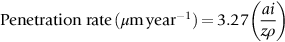
You will need to convert the current density from A m− 2 to μA cm− 2 before putting it into the equation (i value). The answer is 0.045 mm penetration after 5 years.