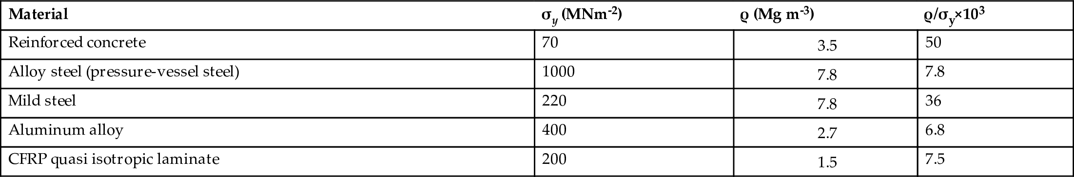
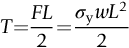
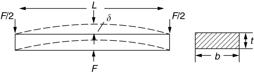
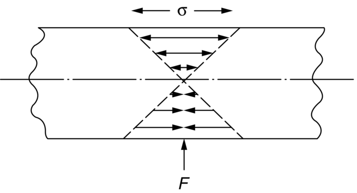
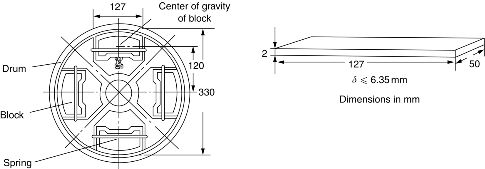
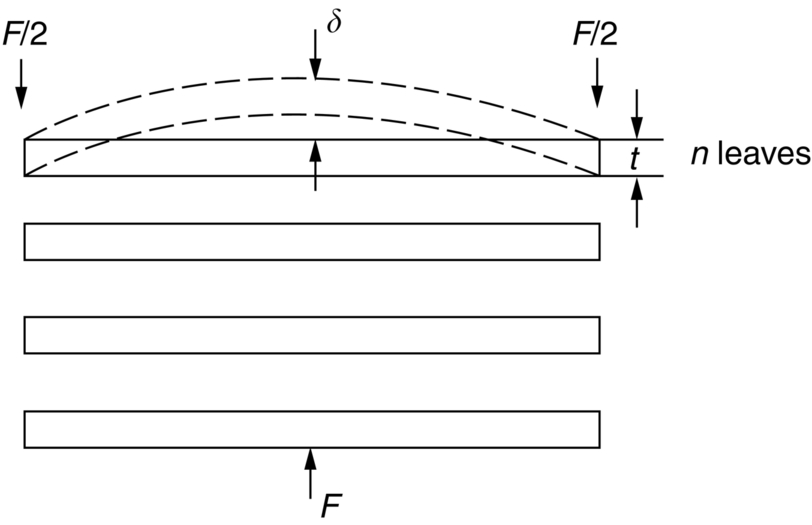
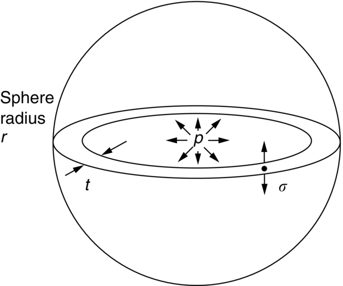
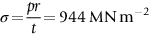
section epub:type=”chapter”> This chapter examines three applications of plasticity. The first (material selection for a spring) requires no plasticity whatever. The second (material selection for a pressure vessel) typifies plastic design of a large structure. It is unrealistic to expect no plasticity: there will always be some, at bolt holes, loading points or changes of section. The important thing is that yielding should not spread entirely through any section of the structure—plasticity must not become general. Finally, this chapter examines an instance (the rolling of metal strip) in which yielding is deliberately induced to give large-strain plasticity. We now examine three applications of plasticity. The first (material selection for a spring) requires no plasticity whatever. The second (material selection for a pressure vessel) typifies plastic design of a large structure. It is unrealistic to expect no plasticity: there will always be some, at bolt holes, loading points, or changes of section. The important thing is that yielding should not spread entirely through any section of the structure—plasticity must not become general. Finally, we examine an instance (the rolling of metal strip) in which yielding is deliberately induced, to give large-strain plasticity. Springs come in many shapes and have many purposes. One thinks of axial springs (a rubber band, for example), leaf springs, helical springs, spiral springs, torsion bars. Regardless of their shape or use, the best material for a spring of minimum volume is that with the greatest value of The argument, at its simplest, is as follows. The primary function of a spring is that of storing elastic energy and—when required—releasing it again. The elastic energy stored per unit volume in a block of material stressed uniformly to a stress σ (see Figure 9.1) is It is this that we wish to maximize. The spring will be damaged if the stress σ exceeds the yield stress or failure stress σy; the constraint is σ ≤ σy. So the maximum energy density is Torsion bars and leaf springs are less efficient than axial springs because some of the material is not fully loaded: the material at the neutral axis, for instance, is not loaded at all. Even leaf springs can take many different forms, but all of them are basically elastic beams loaded in bending. For the loading shown in Figure 13.1, the beam bending results in Chapter 7 give The elastic energy stored in the spring, per unit volume, is Figure 13.2 shows that the stress in the beam is zero along the neutral axis at its center, and is a maximum at the surface, at the midpoint of the beam (because the bending moment is biggest there). The beam bending results in Chapter 7 show that the maximum surface stress is given by Now to be successful, a spring must not undergo a permanent set during use: it must always “spring” back. The condition for this is that the maximum stress must always be less than the yield stress: Eliminating t between this and Equation (13.2) gives So if in service a spring has to undergo a given deflection δ under a force F, the ratio of Springs for a centrifugal clutch Suppose you are asked to select a material for a spring with the following application. A spring-controlled clutch like that shown in Figure 13.3 is designed to transmit 20 horsepower at 800 rpm; the clutch is to begin to pick up load at 600 rpm. The blocks are lined with Ferodo or some other friction material. When properly adjusted, the maximum deflection of the springs is to be 6.35 mm (but the friction pads may wear, and larger deflections may occur; this is a standard problem with springs—they must often withstand extra deflections without losing their sets). The force on the spring is where m is the mass of the block, r the distance of the center of gravity of the block from the center of rotation, and ω the angular velocity. The net force each block exerts on the clutch rim at full speed is where ω2 and ω1 correspond to the angular velocities at 800 and 600 rpm (the net force must be zero for ω2 = ω1, at 600 rpm). The full power transmitted by all four blocks is given by 4μsmr ( μs is the coefficient of static friction and r is specified by the design (the clutch cannot be too big). Power, ω2, and ω1 are specified in Equation (13.7), so m is also specified. The maximum force on the spring is determined by the design from F = mr Given the spring dimensions (t = 2 mm, b = 50 mm, L = 127 mm) and given δ ≤ 6.35 mm, all of which are specified by design, which material should we use? Eliminating F between equations (13.1) and (13.4) gives As well as seeking materials with high values of Table 13.1 shows that spring steel, the cheapest material listed, is adequate for this purpose, but has a worryingly small safety factor to allow for wear of the linings. Only the expensive beryllium–copper alloy, of all the metals shown, would give a significant safety factor (σy/E = 11.5 × 10⁻³). In many designs, the mechanical requirements are such that single springs of the type considered so far would yield even if made from beryllium copper. This commonly arises in the case of suspension springs for vehicles, and so on, where both large δ (“soft” suspensions) and large F (good load-bearing capacity) are required. The solution can then be to use multi-leaf springs (Figure 13.4). t can be made small to give large δ without yield according to while the lost load-carrying capacity resulting from small t can be made up by having several leaves combining to support the load. Finally, materials other than the metals originally listed earlier in Table 13.1 can make good springs. Glass, or fused silica, with σy/E as large as 58 × 10-3 is excellent, provided it operates under protected conditions where it cannot be scratched or suffer impact loading. Nylon is good—provided the forces are low—having σy/E ≈ 22 × 10-3, and it is widely used in household appliances and children’s toys (you probably brushed your teeth with little nylon springs this morning). Leaf springs for heavy trucks are now being made of CFRP: the value of σy/E (6 × 10⁻³) is similar to that of spring steel, and the weight saving compensates for the higher cost. CFRP is always worth examining where an innovative use of materials might offer advantages. We now look at material selection for a pressure vessel able to contain a gas at pressure p, minimizing the weight. We seek a design that will not fail by plastic collapse (i.e., general yield). But we must be cautious: structures can also fail by fast fracture, by fatigue, and by corrosion. We shall discuss these later, but for now we assume that plastic collapse is our only problem. The body of an aircraft, the casing of a solid rocket booster: these are examples of pressure vessels that must be as light as possible. The stress in the vessel wall (Figure 13.5) is: r, the radius of the pressure vessel, is fixed by the design. For safety, σ ≤ σy/S, where S is the safety factor. The vessel mass is giving Substituting for t in Equation (13.10) we find that From Equation (13.13) we have so for the lightest vessel we require the smallest value of (ρ/σy). Table 13.2 gives values of (ρ/σy) for candidate materials. The lightest pressure vessels are made of CFRP, aluminum alloy, and pressure-vessel steel. Reinforced concrete or mild steel results in a very heavy vessel. Of course, CFRP is very expensive, which is why aluminum or high-strength steel is used for things like a aircraft fuselages and SRB casings. Forging, sheet drawing, and rolling are metal-forming processes in which the section of a billet or slab is reduced by compressive plastic deformation. When a slab is rolled (Figure 13.6) the section is reduced from t1 to t2 over a length L as it passes through the rolls. At first sight, it might appear that there would be no sliding (and thus no friction) between the slab and the rolls, since these move with the slab. But the metal is elongated in the rolling direction, so it speeds up as it passes through the rolls, and some slipping is inevitable. If the rolls are polished and lubricated (as they are for precision and cold-rolling) the frictional losses are small. We shall ignore them here (though detailed treatments of rolling include them) and calculate the rolling torque for perfectly lubricated rolls. From the geometry of Figure 13.6 or, if The rolling force F must cause the metal to yield over the length L and width w (normal to Figure 13.6). Thus If the reaction on the rolls appears halfway along L then the torque on each roll is giving The torque required to drive the rolls increases with yield strength σy, so hot-rolling (when σy is low—see Chapter 21) takes less power than cold-rolling. It obviously increases with the reduction in section Rolling can be analyzed in much more detail to include important aspects, which we have ignored: friction, the elastic deformation of the rolls, and the constraint of two-dimensional strain imposed by the rolling geometry. But this case study gives an idea of why an understanding of plasticity, and the yield strength, is important in forming operations, both for metals and polymers.
Case Studies in Yield-Limited Design
Publisher Summary
13.1 Introduction
13.2 Case Study 1: Elastic Design—Materials for Springs
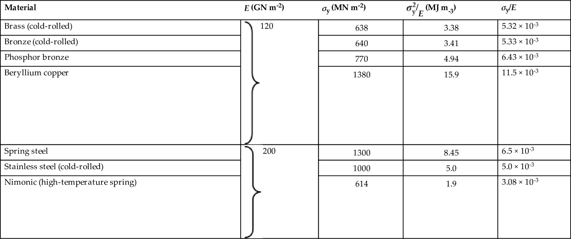
 . Here E is Young’s modulus and σy the failure strength of the material of the spring: its yield strength if ductile, its fracture strength, or modulus of rupture if brittle. Some materials with high values of this quantity are listed in Table 13.1.
The leaf spring
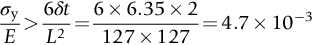
 must be high enough to avoid a permanent set. This is why we have listed values of
  in Table 13.1: the best springs are made of materials with high values of this quantity. For this reason spring materials are heavily strengthened (see Chapter 11): by solid solution strengthening plus work-hardening (cold-rolled, single-phase brass, and bronze), solid solution and precipitate strengthening (spring steel), and so on. Annealing any spring material removes the work-hardening, and may cause the precipitate to coarsen (increasing the particle spacing), reducing σy and making the material useless as a spring.
Worked Example
Mechanics
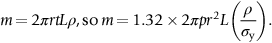
 ) × distance moved per second by inner rim of clutch at full speed, that is
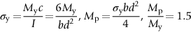
 The requirement that this force deflect the beam by only 6.35 mm with the linings just in contact is what determines the thickness, t, of the spring via Equation (13.1) (L and b are fixed by the design).
Metallic materials for the clutch springs
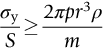
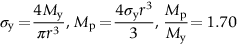
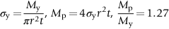
 , we must also ensure that the material we choose meets the criterion of Equation (13.8).
Nonmetallic materials
13.3 Case Study 2: Plastic Design—Materials for Pressure Vessels
13.4 Case Study 3: Large-Strain Plasticity—Metal Rolling

 is small (as it almost always is),
 . And it increases with roll diameter 2r; this is one of the reasons why small-diameter rolls are used, often backed by two or more rolls of larger diameter (to stop them bending).
Examples
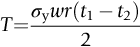
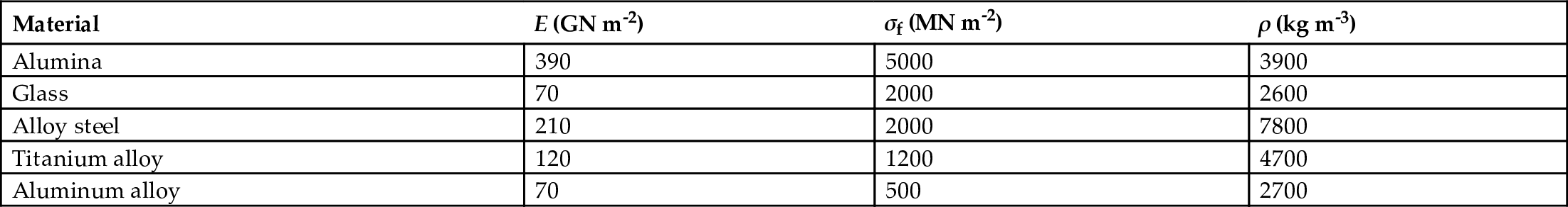
where σf is the yield stress or the compressive fracture stress as appropriate.
The basic design requirement is that the pressure hull has the minimum possible mass compatible with surviving the design pressure.
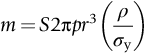
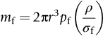
By eliminating t from the equations, show that the minimum mass of the hull is given by the expression
Hence obtain a merit index to meet the design requirement for the failure mechanism. [You may assume that the surface area of the sphere is 4πr2.]
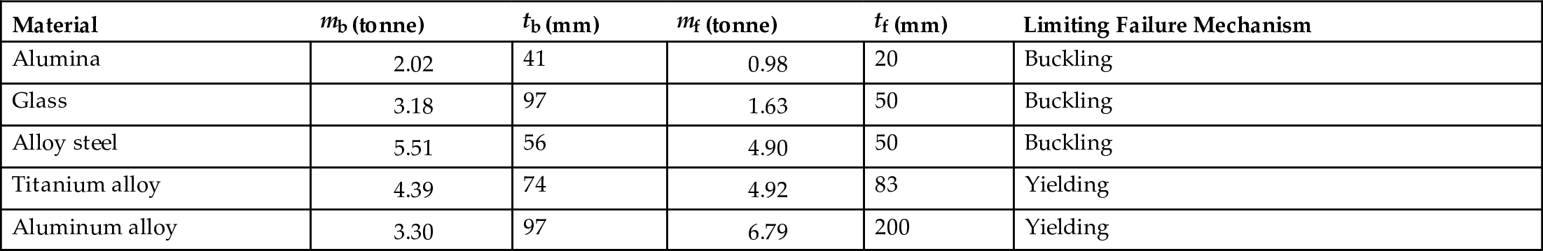
Hence determine the limiting failure mechanism for each material. [Hint: This is the failure mechanism which gives the larger of the two values of t.]
What is the optimum material for the pressure hull? What are the mass, wall thickness, and limiting failure mechanism of the optimum pressure hull?
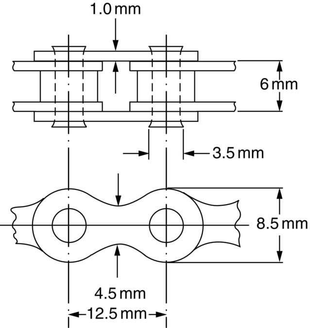
The center of each pedal is 170 mm away from the center of the chain wheel. If the cyclist weighs 90 kg, estimate the factor of safety of the chain. You may assume that a link would fail in simple tension at the position of minimum cross-sectional area and that a pin would fail in double shear. The yield strength of the steel is 1500 Nm m−2.

Answers
The optimum material is alumina, with a mass of 2.02 tonne, a wall thickness of 41 mm, and a limiting failure mechanism of external-pressure buckling.
 .
.  .
.

 120
120 200
200