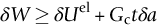
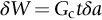
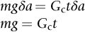
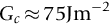
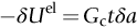
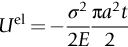
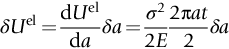
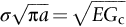
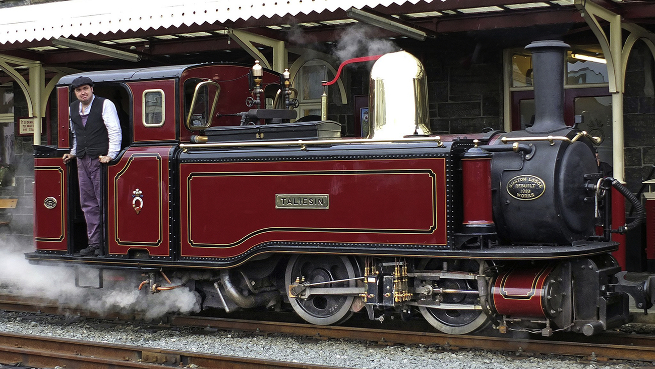
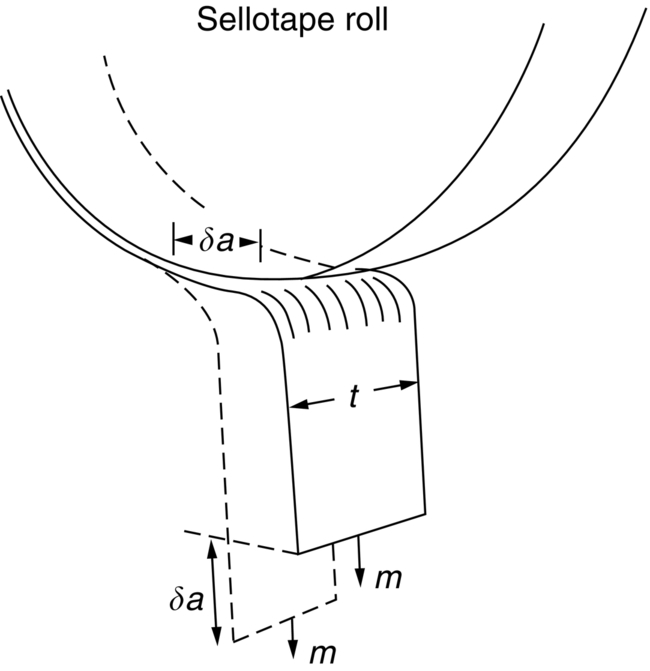
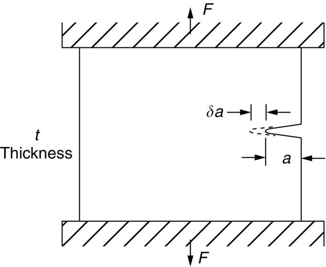
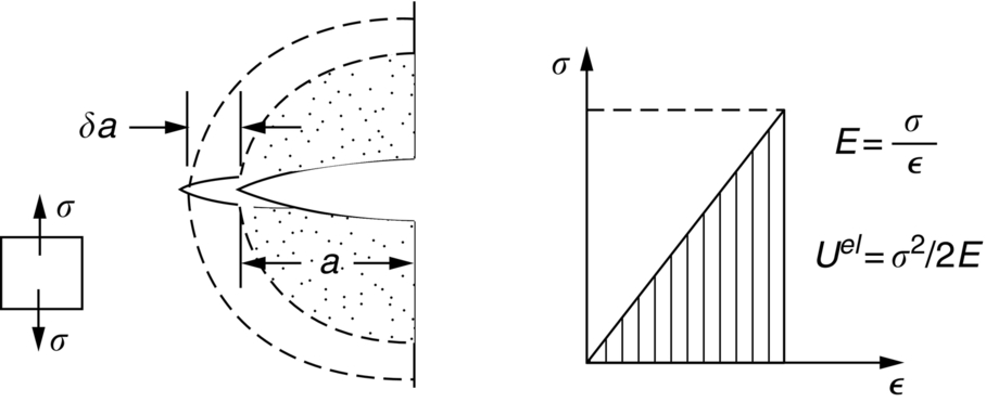
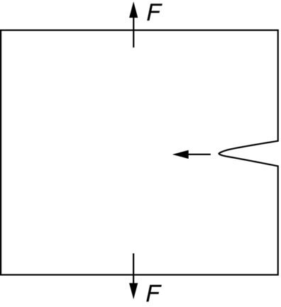
section epub:type=”chapter”> Sometimes structures that were properly designed to avoid both excessive elastic deflection and plastic yielding fail in a catastrophic way by fast fracture. Common to these failures—of things such as welded ships, welded bridges, gas pipelines, and pressure vessels—is the presence of cracks, which is often the result of imperfect welding. Fast fracture is caused by the growth—at the speed of sound in the material—of existing cracks that suddenly became unstable. This chapter discusses the energy criterion for fast fracture by the use of the example of a balloon. If a balloon is blown up, energy is stored in it. There is the energy of the compressed gas in the balloon, and there is the elastic energy stored in the rubber membrane itself. As the pressure is increased, the total amount of elastic energy in the system increases. If then a flaw is introduced into the system, by poking a pin into the inflated balloon, the balloon will explode and all the energy will be released. The chapter presents the data for Gc —toughness (sometimes, critical strain energy release rate)—and Kc —stress intensity factor. Sometimes, structures that were properly designed to avoid both excessive elastic deflection and plastic yielding fail in a catastrophic way by fast fracture. Common to these failures—of things such as welded ships, welded bridges, gas pipelines, and pressure vessels —is the presence of cracks, often the result of imperfect welding. Fast fracture is caused by the growth—at the speed of sound in the material—of existing cracks that suddenly became unstable. Why do they do this? If you blow up a balloon, energy is stored in it. There is the energy of the compressed gas in the balloon, and there is the elastic energy stored in the rubber membrane itself. As you increase the pressure, the total amount of elastic energy in the system increases. If we then introduce a flaw into the system, by poking a pin into the inflated balloon, the balloon will explode, and all this energy will be released. The membrane fails by fast fracture, even though well below its yield strength. But if we introduce a flaw of the same dimensions into a system with less energy in it, as when we poke our pin into a partially inflated balloon, the flaw is stable and fast fracture does not occur. Finally, if we blow up the punctured balloon progressively, we eventually reach a pressure at which it suddenly bursts. In other words, we have arrived at a critical balloon pressure at which our pin-sized flaw is just unstable, and fast fracture just occurs. Why is this? To make the flaw grow, say by 1 mm, we have to tear the rubber to create 1 mm of new crack surface, and this consumes energy: the tear energy of the rubber per unit area × the area of surface torn. If the work done by the gas pressure inside the balloon, plus the release of elastic energy from the membrane itself, is less than this energy the tearing simply cannot take place—it would infringe the laws of thermodynamics. We can, of course, increase the energy in the system by blowing the balloon up a bit more. The crack or flaw will remain stable (i.e., it will not grow) until the system (balloon plus compressed gas) has stored in it enough energy that, if the crack advances, more energy is released than is absorbed. There is, then, a critical pressure for fast fracture of a pressure vessel containing a crack or flaw of a given size. All sorts of accidents (e.g., the sudden collapsing of bridges, the sudden explosion of steam boilers) have occurred—and still do—due to this effect. In all cases, the critical stress—above which enough energy is available to provide the tearing energy needed to make the crack advance—was exceeded, taking the designer by surprise. (Courtesy of Roger Dimmick) The photograph shows a steam locomotive on the Ffestiniog Railway in North Wales, UK. For those interested in such things, it is the World’s oldest operating railway company (founded 1832), and runs for 13 miles on a narrow gauge of 60 cm. Built to transport slate from quarries high in the mountains to the sea port of Porthmadog, it is now a busy tourist railway, and well worth a visit for anyone interested in serious railway engineering.http://www.ffestiniograilway.org.uk/ The working pressure of the boiler is 200 psi (steam locomotive boiler pressures in the UK and US are still quoted in English units of psi—this is an example where one doesn’t want to make mistakes by changing to metric units for no compelling reason, because boilers could blow up if you get the numbers wrong). The boiler is made to modern standards of construction of course, using tough steel plates carefully welded together and thoroughly inspected for manufacturing defects like cracks before being passed for service. In addition, it is given a hydraulic pressure test to 300 psi, to make sure that nothing deforms, distorts, or springs a leak (The boiler is filled with water, and more water is gradually pumped in using a small hand pump until the pressure reaches 300 psi. If any leaks occur, it will not be possible to maintain the pressure without pumping more water in. If a major structural failure does occur under hydraulic testing, nobody will get hurt because the stored energy in compressed water is small – its bulk modulus is large, see Chapter 3.) For a well-maintained boiler, the only real risk of a crack forming is because of thermal fatigue. We will be looking at metal fatigue later in Chapters 18–20. Basically, when a boiler is fired up and steam is raised, the parts expand, and some parts expand more than others, generating internal stresses in the boiler. Every day that the locomotive is in service, the boiler is warmed up in the morning when the fire is lit, and then cooled back down in the evening when the fire is raked out. After many days of this temperature cycling, if there are any design issues with the boiler, a thermal fatigue crack could grow through the steel plate in a thermally stressed location. This would lead to a visible steam leak in service, or a loss of pressure in a hydraulic test. This is an example of what is termed leak before break. The steel and welds are sufficiently tough that a crack—even one large enough to penetrate the steel plate—will not grow by fast fracture. This is an important safety feature in pressure vessel design. (DRHJ was once involved in an incident where there was a crack in a large pressure vessel in a chemical plant. The crack was in a very thick part of the wall, and it had not penetrated through the plate. Under hydraulic test, the crack went critical, and one end of the pressure vessel broke up, dumping many tons of water. This was definitely not “leak before break.” But the hydraulic test had done its job, and found a crack, which could have grown in service and ultimately caused a catastrophic explosion with serious loss of life.)■ We can now write down an energy balance that must be met if a crack is to advance, and fast fracture is to occur. Suppose a crack of length a in a material of thickness t advances by δa, then we require that: work done by loads ≥ change of elastic energy + energy absorbed at the crack tip, that is where Gc is the energy absorbed per unit area of crack (not unit area of new surface), and tδa is the crack area. Gc is a material property—it is the energy absorbed in making a unit area of crack, and we call it the toughness (or, sometimes, the “critical strain energy release rate”). Its units are energy m–2 or J m–2. A high toughness means that it is hard to make a crack propagate (as in copper, for which Gc ≈ 106 J m–2). Glass, on the other hand, cracks very easily; Gc for glass is only ≈ 10 J m–2. This same quantity Gc measures the strength of adhesives. You can measure it for the adhesive used on sticky tape (e.g., Sellotape) by hanging a weight on a partly peeled length while supporting the roll so that it can freely rotate (hang it on a pencil) as shown in Figure 14.1. Increase the load to the value m that just causes rapid peeling (= fast fracture). For this geometry, the quantity δUel is small compared to the work done by m (the tape has comparatively little “give”) and it can be neglected. Then, from our energy formula, for fast fracture. In our case, and therefore, Typically, t = 0.02 m, m = 0.15 kg, and g ≈ 10 m s–2, giving This is a reasonable value for adhesives, and a value bracketed by the values of Gc for many polymers. Naturally, in most cases, we cannot neglect δUel, and must derive more general relationships. Let us first consider a cracked plate of material loaded so that the displacements at the boundary of the plate are fixed. This is a common mode of loading a material—it occurs frequently in welds between large pieces of steel, for example—and is one that allows us to calculate δUel quite easily. The plate shown in Figure 14.2 is clamped under tension so that its upper and lower ends are fixed. Since the ends cannot move, the forces acting on them can do no work, and δW = 0. Accordingly, our energy formula gives, for the onset of fast fracture, Now, as the crack grows into the plate, it allows the material of the plate to relax, so that it becomes less highly stressed, and loses elastic energy. δUel is thus negative, so that –δUel is positive, as it must be since Gc is defined positive. We can estimate δUel in the way shown in Figure 14.3. Let us examine a small cube of material of unit volume inside our plate. Due to the load F this cube is subjected to a stress σ, producing a strain ɛ. Each unit cube therefore has strain energy Uel of σ2/2E (see Figure 9.1). If we now introduce a crack of length a, we can consider that the material in the dotted region relaxes (to zero stress) so as to lose all its strain energy. The energy change is shown in the following equation. As the crack spreads by length δa, we can calculate the appropriate δUel as The critical condition (Equation (14.2)) then gives at onset of fast fracture. Actually, our assumption about the way in which the plate material relaxes is obviously rather crude, and a rigorous mathematical solution of the elastic stresses and strains indicates that our estimate of δUel is too low by exactly a factor of 2. Thus, correctly, we have which reduces to at fast fracture. Another, obviously very common way of loading a plate of material, or any other component for that matter, is simply to hang weights on it (fixed loads) (Figure 14.4). Here the situation is a little more complicated than it was in the case of fixed displacements. As the crack grows, the plate becomes less stiff, and relaxes so that the applied forces move and do work. δW is therefore finite and positive. However, δUel is now positive also (it turns out that some of δW goes into increasing the strain energy of the plate) and our final result for fast fracture is in fact found to be unchanged. Let us now return to our condition for the onset of fast fracture, knowing it to be general for engineering structures The left side of our equation says that fast fracture will occur when, in a material subjected to a stress σ, a crack reaches some critical size a: or, alternatively, when material containing cracks of size a is subjected to some critical stress σ. The right side of our result depends on material properties only; E is obviously a material constant, and Gc, the energy required to generate a unit area of crack, again must depend only on the basic properties of our material. Thus, the important point about the equation is that the critical combination of stress and crack length at which fast fracture commences is a material constant. The term where To summarize: Fast fracture occurs when K = Kc. Kc can be determined experimentally for any material by inserting a crack of known length a into a piece of the material and loading until fast fracture occurs. Gc can be derived from the data for Kc using the relation Table 14.1 ⁎ Values at room temperature unless starred. The values of Kc and Gc range considerably, from the least tough materials such as ice and ceramics, to the toughest such as ductile metals; polymers have intermediate toughness, Gc, but low fracture toughness, Kc (because their moduli are low). However, reinforcing polymers to make composites produces materials having good fracture toughnesses. Finally, although most metals are tough at or above room temperature, when many (e.g., b.c.c. metals such as steels, or c.p.h. metals) are cooled sufficiently, they become quite brittle, as the data show. Obviously these figures for toughness and fracture toughness are extremely important—ignorance of such data has led, and can continue to lead, to engineering disasters of the sort we mentioned at the beginning of this chapter. But just how do these large variations between various materials arise? Why is glass so brittle and annealed copper so tough? We shall explain why in Chapter 15. In Section 14.2 we showed that at onset of fast fracture. Strictly speaking, this result is valid only for a crack through the center of a wide plate of material. In practice, the problems we encounter seldom satisfy this geometry, and a numerical correction to where Y is the numerical correction factor. Values of Y are given at the end of this chapter. However, provided the crack length a is small compared to the width of the plate W, it is usually safe to assume that Y ≈ 1. Case 1 Y = 1 Case 2 Note: When w » a, Y = 1 (Case 1). Examples: When w = 4a, Y = 1.20; when w = 3a, Y = 1.43. Case 3 Y = 1.12 This situation is like one half of Case 1. The factor of 1.12 is added to compensate for introducing a free surface. Case 4 Case 5 Case 6 Note that, for a round hole in uniaxial tension, the stress concentration factor is 3. For a/r = 0 we have a Case 3 crack embedded in a local stress field of 3σ. Thus Y = 3 × 1.12 = 3.36 as shown in the table. Case 7 Note that, for a round hole in equi-biaxial tension, the stress concentration factor is 2. For a/r = 0 we have a Case 3 crack embedded in a local stress field of 2σ. Thus Y = 2 × 1.12 = 2.24. Case 8 Case 9 Y = 0.64 Case 10 Y = 1.12 × 0.64 Values of K can be written differently, or can use different units. This can be very confusing. Conversions are given next. 1 MN m-3/2 = 1 MPa
Fast Fracture and Toughness
Publisher Summary
14.1 Introduction
14.2 Energy Criterion for Fast Fracture
Worked example
Fast fracture at fixed displacements
Fast fracture at fixed loads
Fast-fracture condition
 crops up so frequently in discussing fast fracture that it is usually abbreviated to a single symbol, K, having units MN
  ; it is called the stress intensity factor. Fast fracture therefore occurs when
 is the critical stress intensity factor, more usually called the fracture toughness.
 = fracture toughness (sometimes: critical stress intensity factor); usual units: MN
 = stress intensity factor; usual units: MN
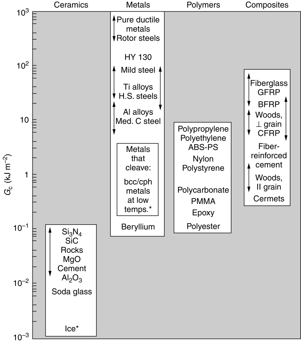
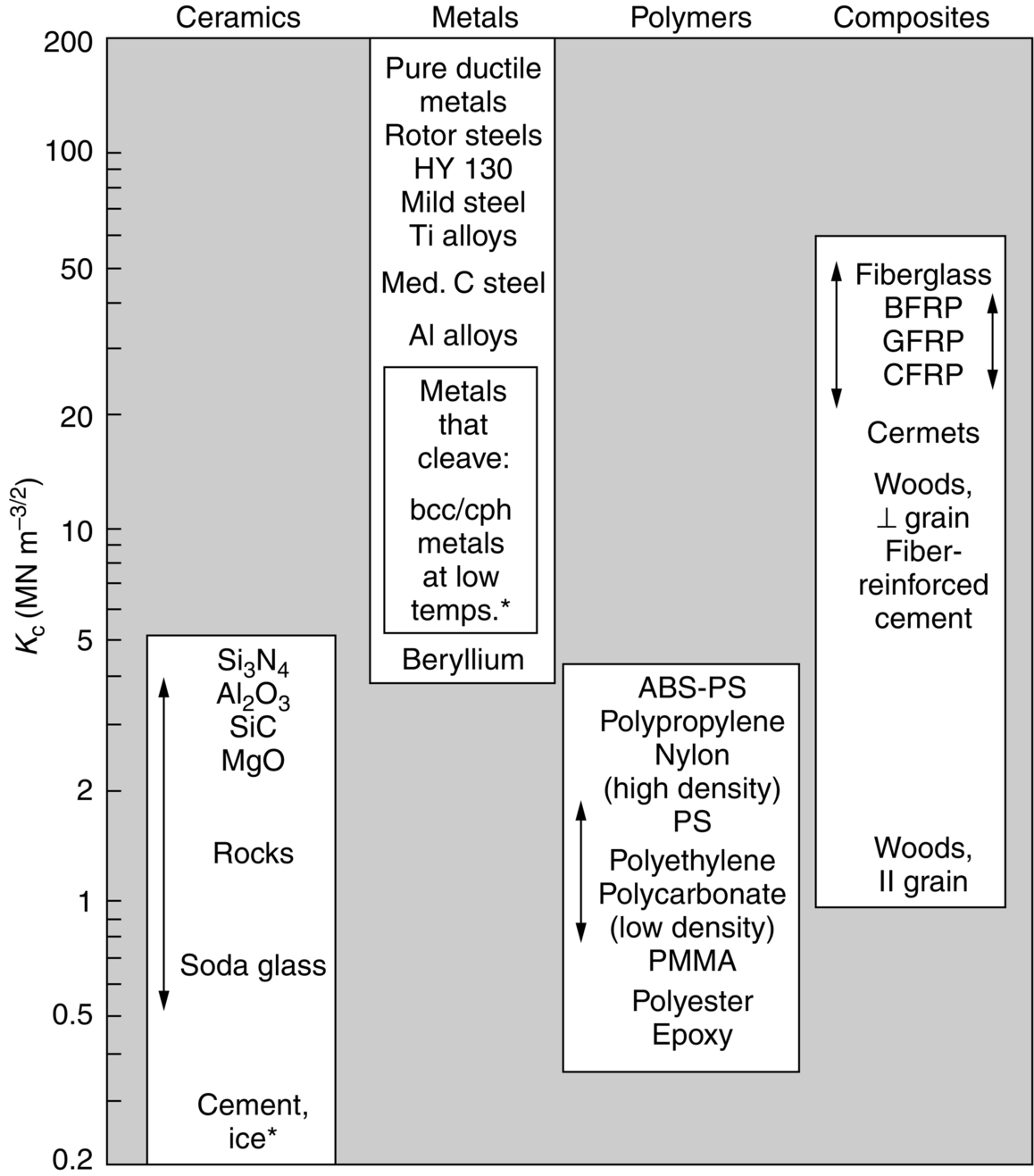
14.3 Data for Gc and Kc
 . Figures 14.5 and 14.6 and Table 14.1 show experimental data for Kc and Gc for a wide range of metals, polymers, ceramics, and composites.
Material
Gc (kJ m−2)
Kc (MN m−3/2)
Pure ductile metals (e.g., Cu, Ni, Ag, Al)
100–1000
100–350
Rotor steels (A533; Discalloy)
220–240
204–214
Pressure-vessel steels (HY130)
150
170
High-strength steels (HSS)
15–118
50–154
Mild steel
100
140
Titanium alloys (Ti6Al4V)
26–114
55–115
GFRPs
10–100
20–60
Fiberglass (glassfiber epoxy)
40–100
42–60
Aluminum alloys (high strength–low strength)
8–30
23–45
CFRPs
5–30
32–45
Common woods, crack ⊥ to grain
8–20
11–13
Boron-fiber epoxy
17
46
Medium-carbon steel
13
51
Polypropylene
8
3
Polyethylene (low density)
6–7
1
Polyethylene (high density)
6–7
2
ABS Polystyrene
5
4
Nylon
2–4
3
Steel-reinforced cement
0.2–4
10–15
Cast iron
0.2–3
6–20
Polystyrene
2
2
Common woods, crack || to grain
0.5–2
0.5–1
Polycarbonate
0.4–1
1.0–2.6
Cobalt/tungsten carbide cermets
0.3–0.5
14–16
PMMA
0.3–0.4
0.9–1.4
Epoxy
0.1–0.3
0.3–0.5
Granite (Westerly granite)
0.1
3
Polyester
0.1
0.5
Silicon nitride, Si3N4
0.1
4–5
Beryllium
0.08
4
Silicon carbide SiC
0.05
3
Magnesia, MgO
0.04
3
Cement/concrete, unreinforced
0.03
0.2
Calcite (marble, limestone)
0.02
0.9
Alumina, Al2O3
0.02
3–5
Shale (oilshale)
0.02
0.6
Soda glass
0.01
0.7–0.8
Electrical porcelain
0.01
1
Ice
0.003
0.2⁎
Note on the stress intensity factor, K
 is required to get the strain energy calculation right. In general we write:
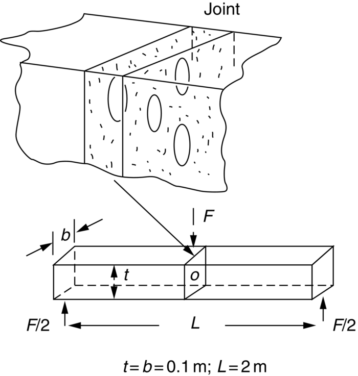
Examples
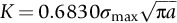
 , calculate the maximum load F that the beam can support. Assume K = Y
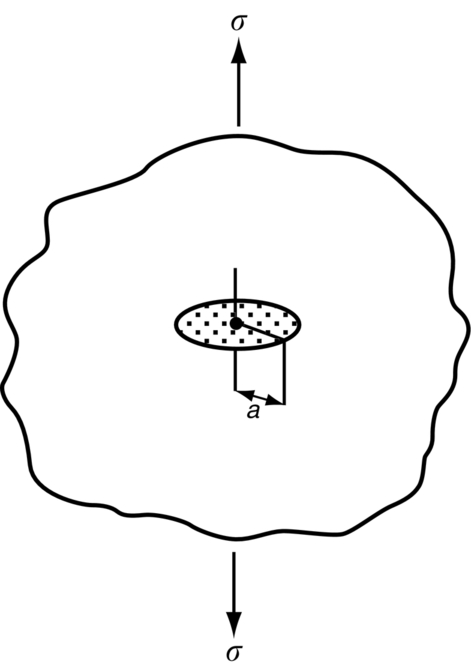
 for the disc-shaped bubbles, where Y = 0.64. Use Equation (13.3), and make sure that you convert a into meters before you put it into the fast fracture equation.
 m and a yield strength of 500 MN m−2. Assuming that the plate contains cracks on the limit of detection, determine whether the plate will undergo general yield or will fail by fast fracture before general yielding occurs. What is the stress at which fast fracture would occur? (Y = 1.12 for the edge crack.)
 . At cruising altitude, the internal gauge pressure is 0.06 MN m−2. Multiple fatigue cracks initiated at a horizontal row of rivet holes, and linked to form a single long axial through thickness crack in the fuselage. Estimate the critical length at which this crack will run, resulting in the break-up of the fuselage. The hoop stress in a thin-walled tube is given by
  (see Example 7.5).
 compared to a value when new of about 80. The loss in toughness was due to temper embrittlement caused by the impurity phosphorus.
The skin of the flue was made from plate 10 mm thick. Owing to the self-weight of the flue the plate has to withstand primary membrane stresses of up to 60 MN m−2. Estimate the length of through-thickness crack that will lead to the fast fracture of the flue when the plant is shut down.
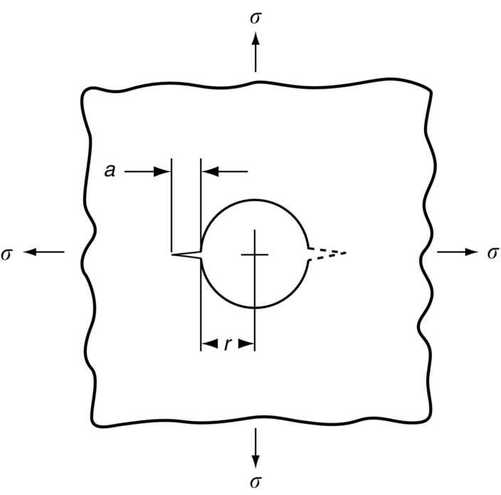
 . Given that the hole introduces a local stress concentration factor of 3, account for the failure using fracture mechanics. Assume that Y = 1.2.
After 16 years in service the vessel exploded into a large number of fragments, some of which were hurled a distance of 1 km. Semicircular “thumbnail” cracks, typically 6 mm deep, were found at the inner surface of the vessel; they had initiated at the edges of a series of fillet welds used to attach internal fittings to the vessel wall. The gas in the vessel contained 58% hydrogen and the cracks were blamed on hydrogen cracking.
Tests on samples of the steel gave a value for Kc of about 40 MN  . Account for the failure using fracture mechanics. You should assume that there is a residual tensile stress of 100 MN m−2 at the welds in addition to the hoop stress. (Y = 0.72 for the thumbnail cracks)
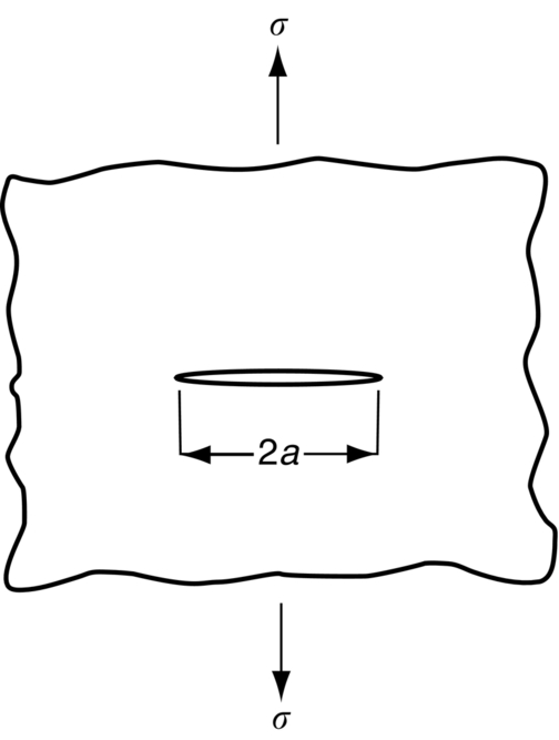
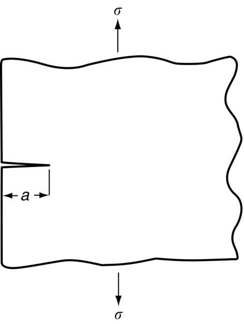
Case 1
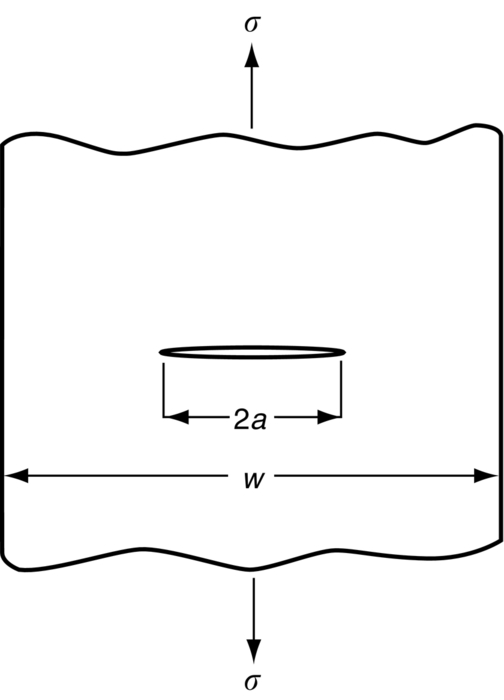
Case 2 (w = 4a)
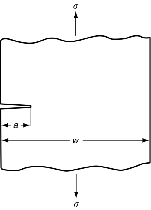
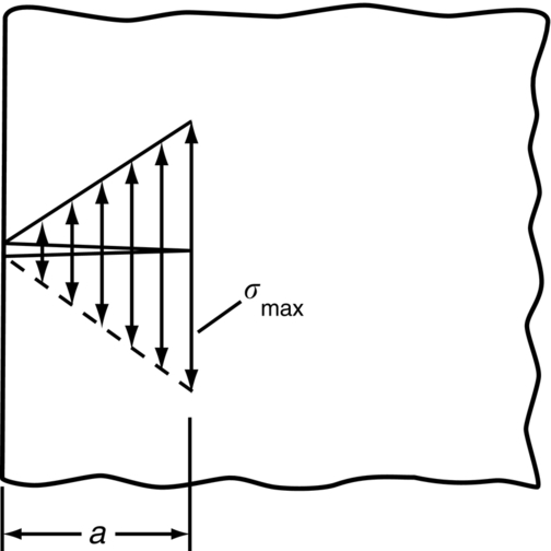
Case 3
Case 4 (w = 5a)
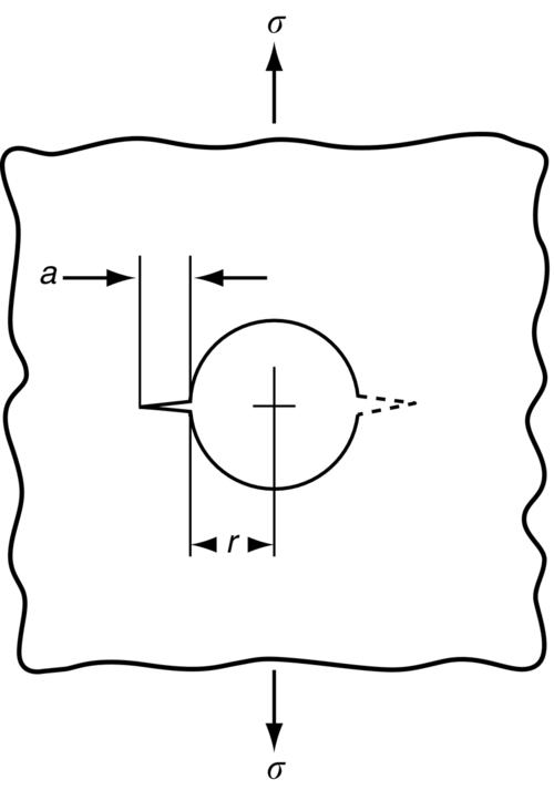
Case 6 (one crack, a/r = 0.2)
Case 9
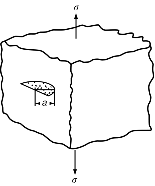
Case 10
Explain why this method works so well. (Hint: in Table 14.1, compare the value of Kc for soda glass with the values of Kc for the other materials listed.)
Answers
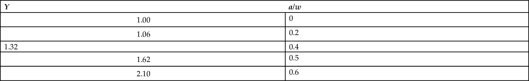
Y Values
Y (one crack)
Y (two cracks)
a/r
3.36
3.36
0
2.73
2.73
0.1
2.30
2.41
0.2
1.86
1.96
0.4
1.64
1.71
0.6
1.47
1.58
0.8
1.37
1.45
1.0
1.18
1.29
1.5
0.71
1.00 (Case 1)
∞
Y (one crack)
Y (two cracks)
a/r
2.24
2.24
0
1.98
1.98
0.1
1.82
1.83
0.2
1.58
1.61
0.4
1.42
1.52
0.6
1.32
1.43
0.8
1.22
1.38
1.0
1.06
1.26
1.5
0.71
1.00
∞
K Conversions
 = 31.6 N mm–3/2 = 31.6 MPa
  = 0.907 ksi
  (kilopounds per sq. in.
  )
)