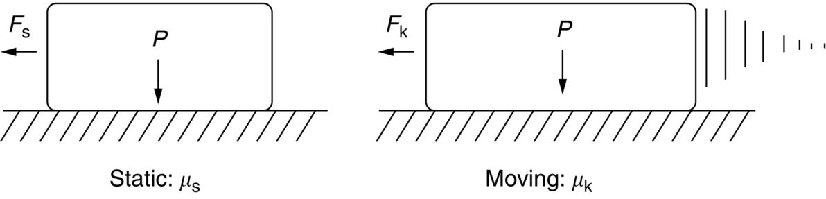
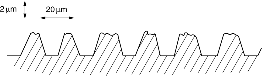
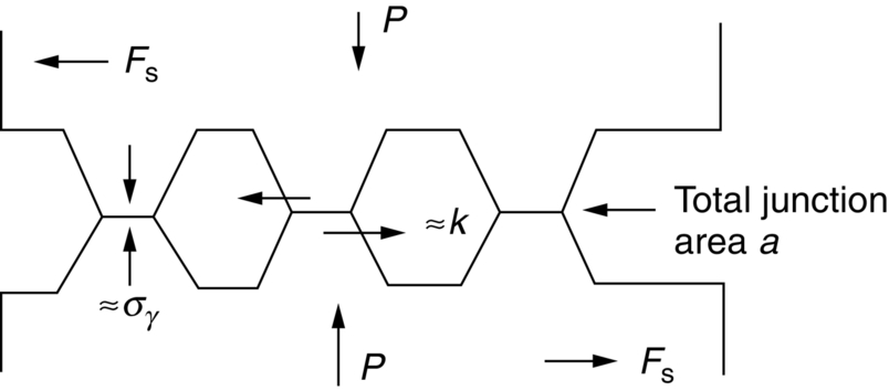
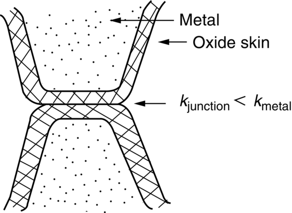
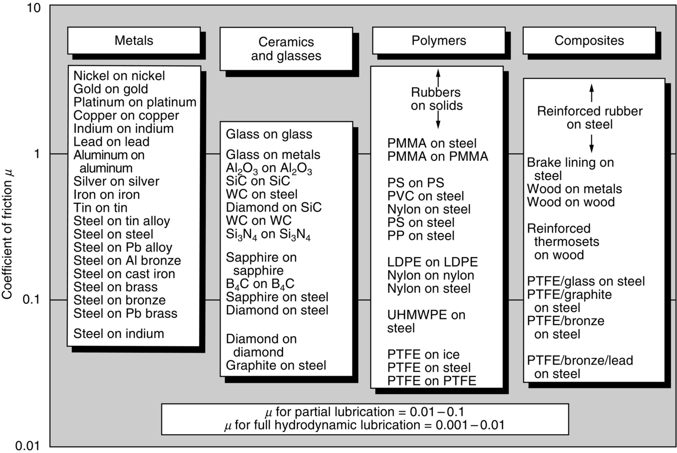
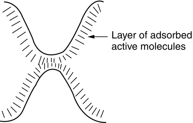
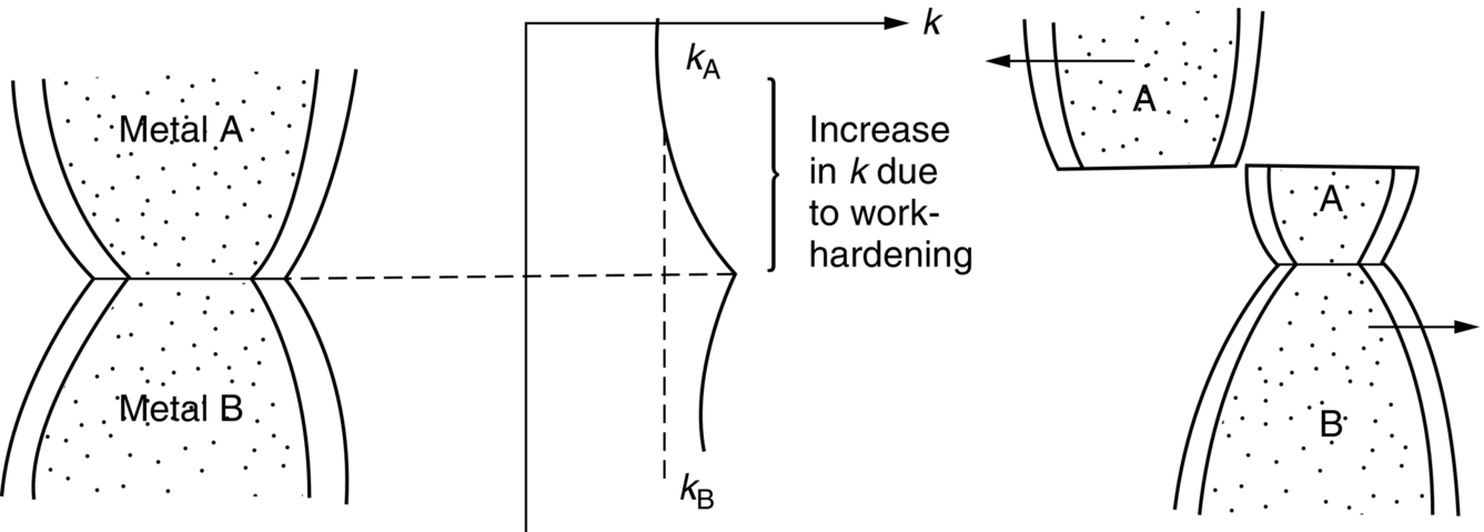
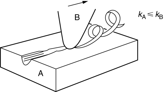
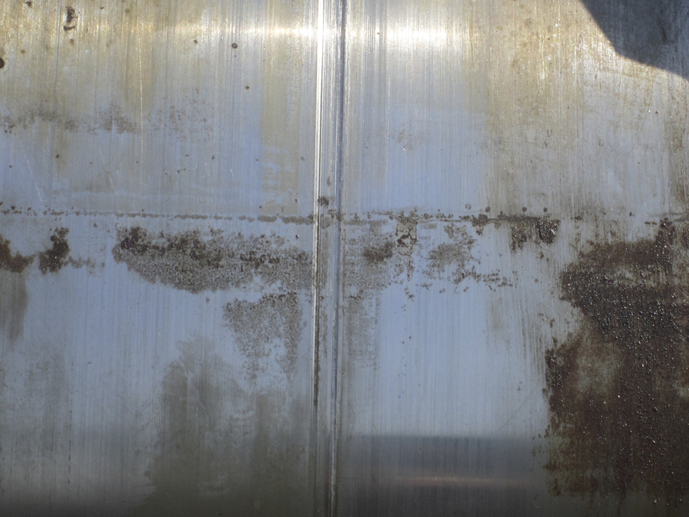
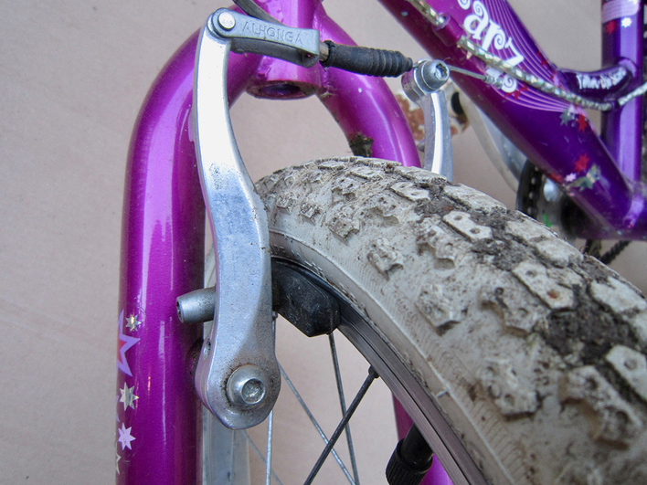
section epub:type=”chapter”> This chapter discusses the frictional properties of materials in contact. This is of considerable importance in mechanical design. Frictional forces are undesirable in bearings because of the power they waste; and wear is bad because it leads to poor working tolerances and ultimately to failure. On the other hand, when selecting materials for clutch and brake linings—or even for the soles of shoes—the aim is to maximize friction but still to minimize wear. But wear is not always bad—for example, in operations such as grinding and polishing, the aim is to achieve maximum wear with the minimum of energy expended in friction. Without wear, one could not write with chalk on a blackboard or with a pencil on paper. The chapter examines the origins of friction and wear and explores case studies that illustrate the influence of friction and wear on component design. When two materials are placed in contact, any attempt to cause one of the materials to slide over the other is resisted by a friction force. The chapter presents the data for coefficients of friction and lubrication. Even when solid surfaces are protected by oxide films and boundary lubricants, some solid-to-solid contact occurs at regions where the oxide film breaks down under mechanical loading, and adsorption of active boundary lubricants is poor. This intimate contact will generally lead to wear. Wear is normally divided into two main types: adhesive and abrasive wear. The chapter concludes with a discussion of surface and bulk properties. We now look at the frictional properties of materials in contact, and the wear that results when such contacts slide. This is of considerable importance in mechanical design. Frictional forces are undesirable in bearings because of the power they waste; and wear is bad because it leads to poor working tolerances, and ultimately to failure. On the other hand, when selecting materials for clutch and brake linings—or even for the soles of shoes—we aim to maximize friction but still to minimize wear, for obvious reasons. But wear is not always bad: in operations such as grinding and polishing, we try to achieve maximum wear with the minimum of energy expended in friction; and without wear you could not write with chalk on a board, or with a pencil on paper. In this chapter and the next we examine the origins of friction and wear and then explore case studies that illustrate the influence of friction and wear on component design. As you know, when two materials are placed in contact, any attempt to cause one of the materials to slide over the other is resisted by a friction force (Figure 29.1). The force that will just cause sliding to start, Fs, is related to the force P acting normal to the contact surface by where μs is the coefficient of static friction. Once sliding starts, the limiting frictional force decreases and we can write where μk (<μs) is the coefficient of kinetic friction (Figure 29.1). The work done in sliding against kinetic friction appears as heat. These results at first sight run counter to our intuition—how is it that the friction between two surfaces can depend only on the force P pressing them together and not on their area? In order to understand this behavior, we must first look at the geometry of a typical surface. If the surface of a fine-turned bar of metal is examined by making an oblique slice through it (a “taper section” which magnifies the height of any asperities), or if its profile is measured with a profilometer, it is found that the surface looks like Figure 29.2. The figure shows a large number of projections or asperities—it looks rather like a cross-section through Switzerland. If the metal is abraded with the finest abrasive paper, the scale of the asperities decreases but they are still there—just smaller. Even if the surface is polished for a long time using the finest type of metal polish, micro-asperities still survive. So it follows that, if two surfaces are placed in contact, no matter how carefully they have been machined and polished, they will contact only at the occasional points where one set of asperities meets the other. It is rather like turning Austria upside down and putting it on top of Switzerland. The load pressing the surfaces together is supported solely by the contacting asperities. The real area of contact, a, is very small and because of this the stress P/a (load/area) on each asperity is very large. Initially, at very low loads, the asperities deform elastically where they touch. However, for realistic loads, the high stress causes extensive plastic deformation at the tips of asperities. If each asperity yields, forming a junction with its partner, the total load transmitted across the surface (Figure 29.3) is where σy is the compressive yield stress. In other words, the real area of contact is given by Obviously, if we double P we double the real area of contact, a. Let us now look at how this contact geometry influences friction. If you attempt to slide one of the surfaces over the other, a shear stress Fs/a appears at the asperities. The shear stress is greatest where the cross-sectional area of asperities is least, that is, at the contact plane. Now, the intense plastic deformation in the regions of contact presses the asperity tips together so well that there is atom-to-atom contact across the junction. The junction, therefore, can withstand a shear stress as large as k approximately, where k is the shear-yield strength of the material (Chapter 12). The asperities will give way, allowing sliding, when or, since k ≈ σy/2, when Combining this with Equation (29.3), we have This is just the empirical Equation (29.1) we started with, with μs ≈ 1/2, but this time it is not empirical—we derived it from a model of the sliding process. The value μs ≈ 1/2 is close to the value of coefficients of static friction between unlubricated metal, ceramic, and glass surfaces—a considerable success. How do we explain the lower value of μk? Well, once the surfaces are sliding, there is less time available for atom-to-atom bonding at the asperity junctions than when the surfaces are in static contact, and the contact area over which shearing needs to take place is correspondingly reduced. As soon as sliding stops, creep allows the contacts to grow a little, diffusion allows the bond there to become stronger, and μ rises again to μs. If metal surfaces are thoroughly cleaned in vacuum it is almost impossible to slide them over each other. Any shearing force causes further plasticity at the junctions, which quickly grow, leading to complete seizure (μ > 5). This is a problem in outer space, and in atmospheres (e.g., H2) that remove any surface films from the metal. A little oxygen or H2O greatly reduces μ by creating an oxide film that prevents these large metallic junctions forming. We said in Chapter 25 that all metals except gold have a layer, no matter how thin, of metal oxide on their surfaces. Experimentally, it is found that for some metals the junction between the oxide films formed at asperity tips is weaker in shear than the metal on which it grew (Figure 29.4). In this case, sliding of the surfaces will take place in the thin oxide layer, at a stress less than in the metal itself, and lead to a corresponding reduction in μ to a value between 0.5 and 1.5. When soft metals slide over each other (e.g., lead on lead, Figure 29.5) the junctions are weak but their area is large so μ is large. When hard metals slide (e.g., steel on steel) the junctions are small, but they are strong, and again friction is large (Figure 29.5). Many bearings are made of a thin film of a soft metal between two hard ones, giving weak junctions of small area. White metal bearings, for example, consist of soft alloys of lead or tin supported in a matrix of stronger phases; bearing bronzes consist of soft lead particles (which smear out to form the lubricating film) supported by a bronze matrix; and polymer-impregnated porous bearings are made by partly sintering copper with a polymer (usually PTFE) forced into its pores. Bearings such as these are not designed to run dry—but if lubrication does break down, the soft component gives a coefficient of friction of 0.1 to 0.2 which may be low enough to prevent catastrophic overheating and seizure. When ceramics slide on ceramics (Figure 29.5), friction is lower. Most ceramics are very hard—good for resisting wear—and, because they are stable in air and water (metals, except gold, are not genuinely stable, even if they appear so)—they have less tendency to bond, and shear more easily. When metals slide on bulk polymers, friction is still caused by adhesive junctions, transferring a film of polymer to the metal. And any plastic flow tends to orient the polymer chains parallel to the sliding surface, and in this orientation they shear easily, so μ is low—0.05 to 0.5 (Figure 29.5). Polymers make attractive low-friction bearings, although they have some drawbacks: polymer molecules peel easily off the sliding surface, so wear is heavy; and because creep allows junction growth when the slider is stationary, the coefficient of static friction, μs, is larger than that for sliding friction, μk. Composites can be designed to have high friction (brake linings) or low friction (PTFE/bronze/lead bearings), as shown in Figure 29.5. More of this later. As we said in the introduction, friction absorbs a lot of work in machinery and as well as wasting power, this work is mainly converted to heat at the sliding surfaces, which can damage and even melt the bearing. In order to minimize frictional forces we need to make it as easy as possible for surfaces to slide over one another. The obvious way to try to do this is to contaminate the asperity tips with something that: (a) can stand the pressure at the bearing surface and so prevent atom-to-atom contact between asperities; (b) can itself shear easily. Polymers and soft metal, as we have said, can do this; but we would like a much larger reduction in μ than these can give, and then we must use lubricants. The standard lubricants are oils, greases, and fatty materials such as soap and animal fats. These “contaminate” the surfaces, preventing adhesion, and the thin layer of oil or grease shears easily, obviously lowering the coefficient of friction. What is not so obvious is why the very fluid oil is not squeezed out from between the asperities by the enormous pressures generated there. One reason is that nowadays oils have added to them small amounts (≈1%) of active organic molecules. One end of each molecule reacts with the metal oxide surface and sticks to it, while the other ends attract one another to form an oriented “forest” of molecules (Figure 29.6), rather like mold on cheese. These forests can resist very large forces normal to the surface (and hence separate the asperity tips very effectively) while the two layers of molecules can shear over each other quite easily. This type of lubrication is termed partial or boundary lubrication, and is capable of reducing μ by a factor of 10 (Figure 29.5). Hydrodynamic lubrication is even more effective: we shall discuss it in the next chapter. Even the best boundary lubricants cease to work above about 200°C. Soft metal bearings such as those described earlier can cope with local hot-spots: the soft metal melts and provides a local lubricating film. But when the entire bearing is designed to run hot, special lubricants are needed. The best are a suspension of PTFE in special oils (good to 320°C); graphite (good to 600°C); and molybdenum disulfide (good to 800°C). Even when solid surfaces are protected by oxide films and boundary lubricants, some solid-to-solid contact occurs at regions where the oxide film breaks down under mechanical loading, and adsorption of active boundary lubricants is poor. This intimate contact will generally lead to wear. Wear is normally divided into two main types: adhesive and abrasive wear. Figure 29.7 shows that, if the adhesion between A and B atoms is good enough, wear fragments will be removed from the softer material A. If materials A and B are the same, wear takes place from both surfaces—the wear bits fall off and are lost or get trapped between the surfaces and cause further trouble (see below). The size of the bits depends on how far away from the junction the shearing takes place: if work-hardening extends well into the asperity, the tendency will be to produce large pieces. To minimize the rate of wear we obviously need to minimize the size of each piece removed. The obvious way to do this is to minimize the area of contact a. Since a ≈ P/σy reducing the loading on the surfaces will reduce the wear, as would seem intuitively obvious. Try it with chalk on a board (see Figure 29.8): the higher the pressure, the stronger the line (a wear track). The second way to reduce a is to increase σy (i.e., the hardness). This is why hard pencils write with a lighter line than soft pencils. Wear fragments produced by adhesive wear often become detached from their asperities during further sliding of the surfaces. Because oxygen is desirable in lubricants (to help maintain the oxide-film barrier between the sliding metals) these detached wear fragments can become oxidized to give hard oxide particles which abrade the surfaces in the way that sandpaper might. Figure 29.9 shows how a hard material can “plough” wear fragments from a softer material, producing severe abrasive wear. Abrasive wear is not, of course, confined to indigenous wear fragments, but can be caused by dirt particles (e.g., sand) making their way into the system, or—in an engine—by combustion products: that is why it is important to filter the oil. Obviously, the rate of abrasive wear can be reduced by reducing the load—just as in a hardness test. The particle will dig less deeply into the metal, and plough a smaller furrow. Increasing the hardness of the metal will have the same effect. Although abrasive wear is often bad (Figure 29.10) we would find it difficult to sharpen tools, or polish brass, or drill rock, without it. Many considerations enter the choice of material for a bearing. It must have bulk properties that meet the need to support loads and transmit heat fluxes. It must be processable: that is, capable of being shaped, finished, and joined. It must meet certain economic criteria: limits on cost, availability, and suchlike. If it can do all these things it must further have—or be given—necessary surface properties to minimize wear, and, when necessary, resist corrosion. So, bearing materials are not chosen for their wear or friction properties (their “tribological” properties) alone; they have to be considered in the framework of the overall design. One way forward is to choose a material with good bulk properties, and then customize the surface with treatments or coatings. For the most part, it is the properties of the surface that determine tribological response, although the immediate subsurface region is obviously important because it supports the surface itself. There are two general ways of tailoring surfaces. The aim of both is to increase the surface hardness, or to reduce friction, or all of these. The first is surface treatment involving only small changes to the chemistry of the surface. They exploit the increase in the hardness given by embedding foreign atoms in a thin surface layer: in carburizing (carbon), nitriding (nitrogen), or boriding (boron), the surface is hardened by diffusing these elements into it from a gas, liquid, or solid powder at high temperatures. Steels, which already contain carbon, can be surface-hardened by rapidly heating and then cooling their surfaces with a flame, an electron beam, or a laser. Elaborate though these processes sound, they are standard procedures, widely used, and to very good effect. The second approach, that of surface coating, is more difficult, and that means more expensive. But it is often worth it. Hard, corrosion-resistant layers of alloys rich in tungsten, cobalt, chromium, or nickel can be sprayed onto surfaces, but a refinishing process is usually necessary to restore the dimensional tolerances. Hard ceramic coatings such as Al2O3, Cr2O3, TiC, or TiN can be deposited by plasma methods and these not only give wear resistance but resistance to oxidation and other sorts of chemical attack as well. And—most exotic of all—it is now possible to deposit diamond (or something very like it) on to surfaces to protect them from almost anything. The following photograph shows the brake mechanism on a bicycle. The circumferential braking force is produced by friction between the brake blocks (made from rubber) and the metal rim of the wheel. The brake blocks are pressed into contact with the wheel rim (“normal” force) by the calipers, which are connected by a wire cable to the brake lever on the handlebars. This system works well in dry conditions. In wet conditions, however, the braking performance is not as good. This is because the water acts as a boundary lubricant between the rubber and the metal (see Section 29.4). There are various solutions to this problem, such as enclosed drum brakes (like those on old cars) and disc brakes (like those on modern cars). But these tend to have cost or weight penalties. So is it worth investigating different materials for caliper brakes? Experiments show that changing the rubber of the brake block does not make much difference. But changing the metal of the rim does. The wheel rims of older bikes are made from steel, but plated with chromium. So the frictional pair is Rubber/Cr. Modern bikes have aluminum alloy rims, so the frictional pair is Rubber/Al. Rubber/Cr has significantly better dry braking performance than Rubber/Al. But in wet conditions, the braking performance of Rubber/Cr is very poor. Wet Rubber/Al is a lot better than wet Rubber/Cr. The solution adopted in modern bikes is to increase the mechanical advantage between the brake lever and the brake blocks, roughly doubling the normal force, which brings the dry performance of Rubber/Al into line with that of Rubber/Cr, while benefitting from the reasonable wet performance of Rubber/Al. Older Rubber/Cr bikes with lower normal forces are good in dry conditions, but are hazardous in wet conditions. There are two other complications in caliper brake design. First, there is an upper limit on the normal force, equal to the force, which will bend the wheel rim inwards (and force it into the tire). Second, at quite modest values of the normal force P, the frictional force Fk for Rubber/Metal starts to deviate below that predicted by Equation (29.2), so further increasing the normal force produces rapidly diminishing returns. We will look at the complications of frictional pairs involving rubber in the next Chapter (Section 30.4).
Friction and Wear
Publisher Summary
29.1 Introduction
29.2 Friction between Materials
29.3 Coefficients of Friction
29.4 Lubrication
29.5 Wear of Materials
Adhesive wear

Abrasive wear
29.6 Surface and Bulk Properties
Worked Example
Examples
Answers