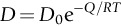
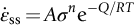
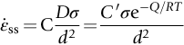
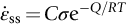
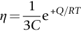
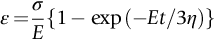
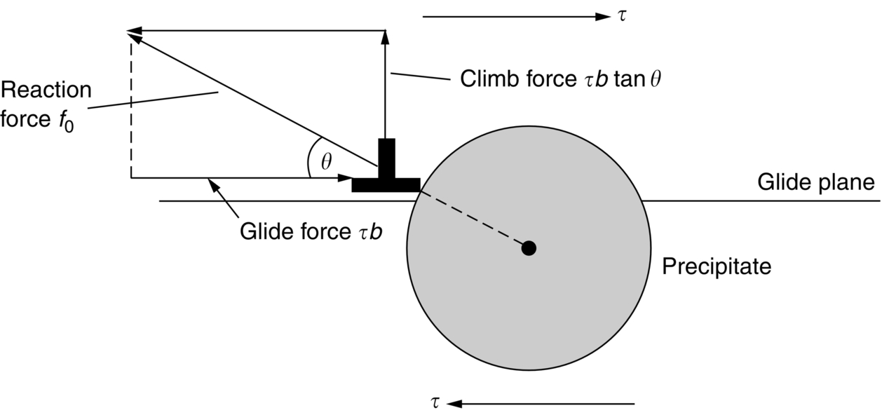
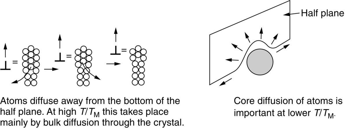
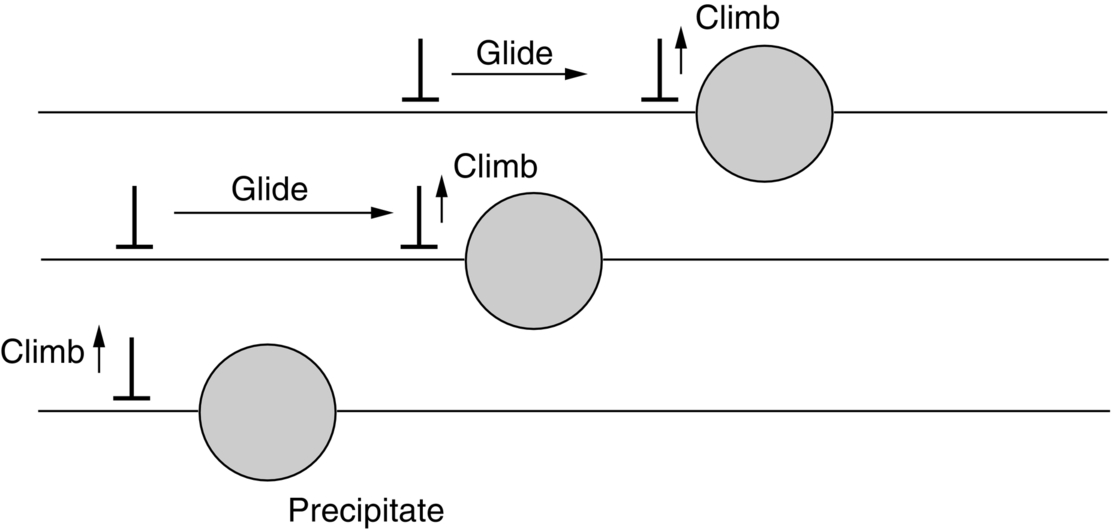
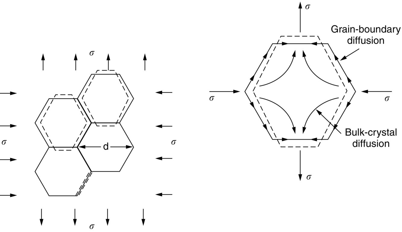
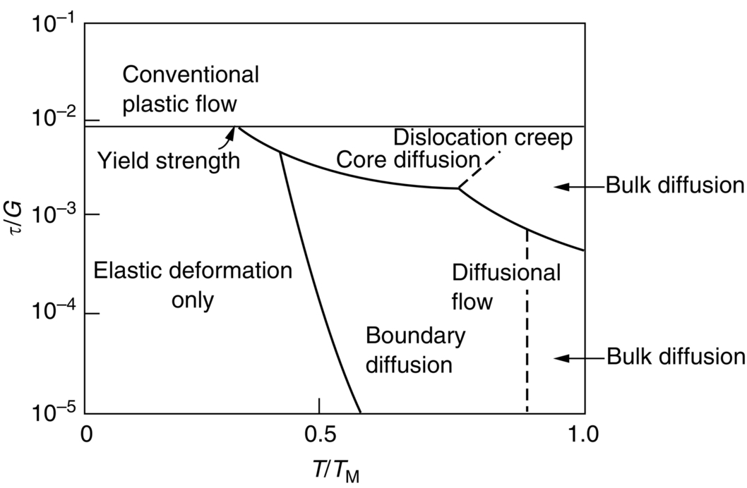
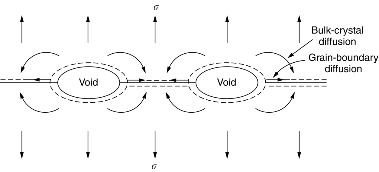
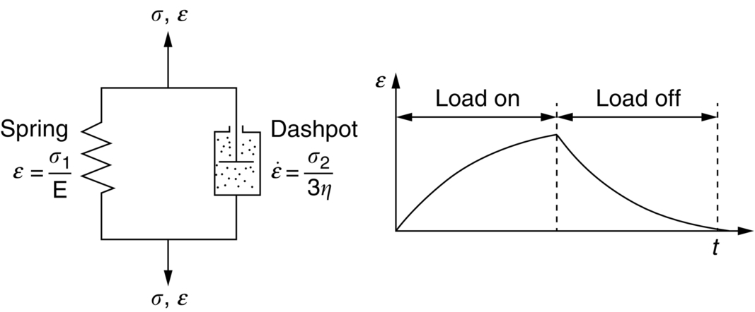
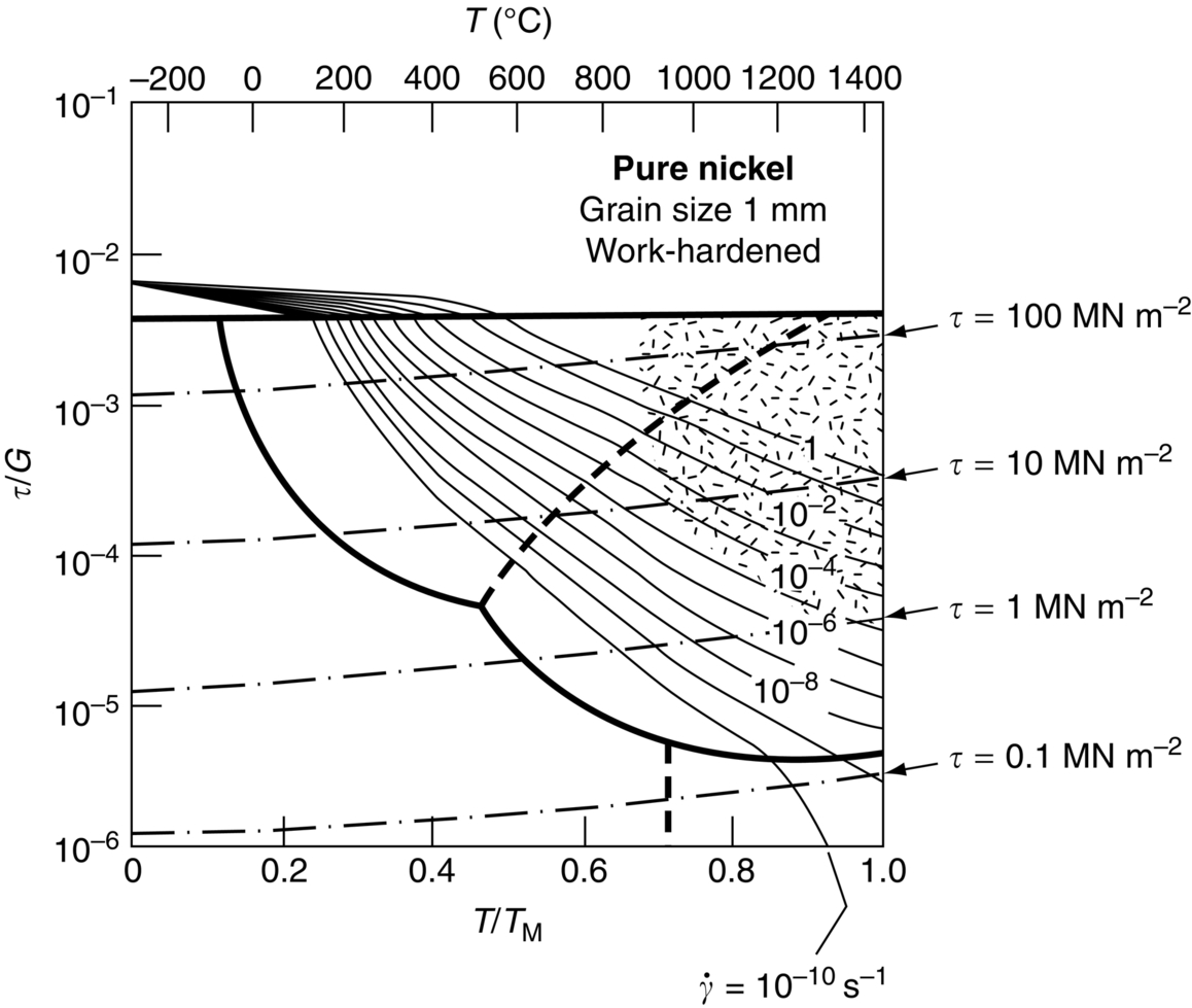
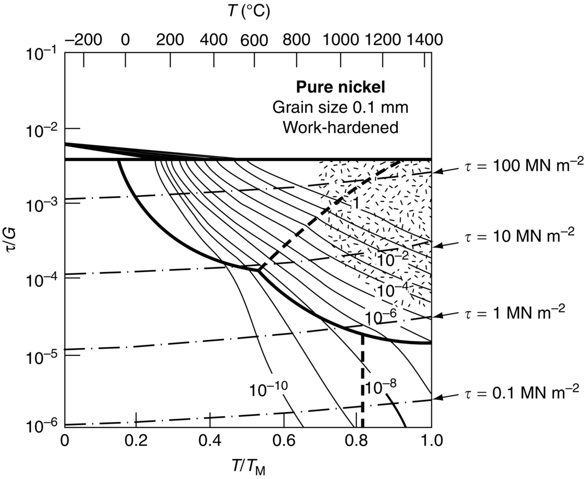
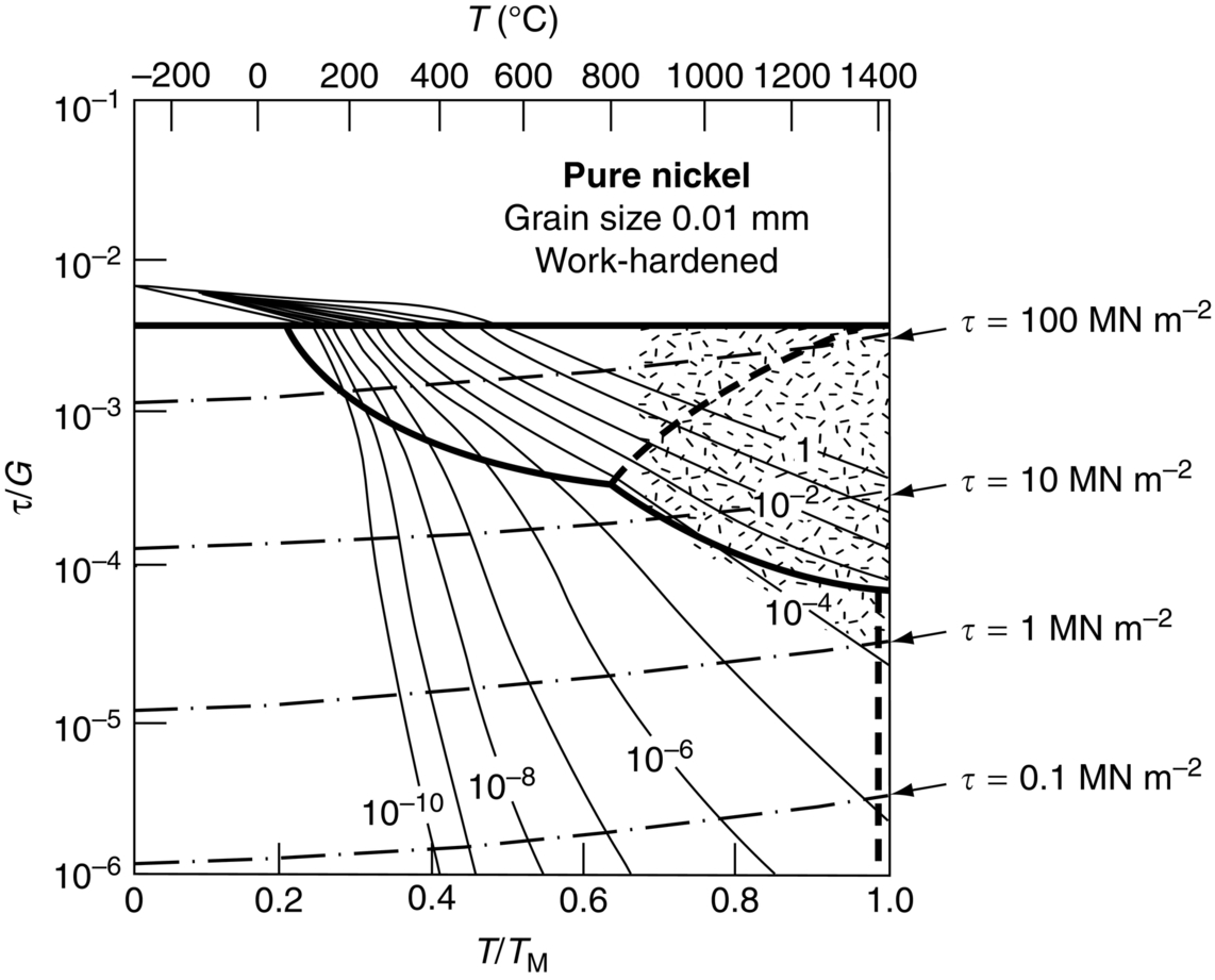
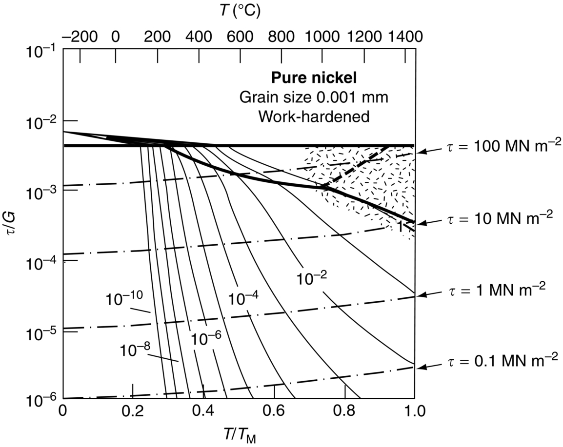
section epub:type=”chapter”> When a material is loaded at high temperature it creeps—that is, it deforms continuously and permanently at a stress that is less than the stress that would cause permanent deformation at room temperature. To understand how to make engineering materials more resistant to creep deformation and creep fracture, one must first look at how creep and creep-fracture take place on an atomic level. There are two mechanisms of creep: dislocation creep (which gives power-law behavior) and diffusion creep (which gives linear-viscous creep). The rate of both is usually limited by diffusion, so both follow Arrhenius’s law. Creep fracture, too, depends on diffusion. Diffusion becomes appreciable at about 0.3TM—that is why materials start to creep above this temperature. Creep of polymers is a major design problem. The chapter describes the creep mechanisms of polymers. The chapter concludes with a discussion of the process of selection of materials that resist creep. In Chapter 21 we showed that when a material is loaded at high temperature it creeps, that is, it deforms continuously and permanently at a stress that is less than the stress that would cause permanent deformation at room temperature. In order to understand how we can make engineering materials more resistant to creep deformation and creep fracture, we must first look at how creep and creep-fracture take place on an atomic level, that is, we must identify and understand the mechanisms by which they take place. There are two mechanisms of creep: dislocation creep (which gives power-law behavior) and diffusion creep (which gives linear-viscous creep). The rate of both is usually limited by diffusion, so both follow Arrhenius’s law. Creep fracture, too, depends on diffusion. Diffusion becomes appreciable at about 0.3TM—that is why materials start to creep above this temperature. As we saw in Chapter 11, the stress required to make a crystalline material deform plastically is that needed to make the dislocations in it move. Their movement is resisted by (a) the intrinsic lattice resistance, and (b) the obstructing effect of obstacles (e.g., dissolved solute atoms, precipitates formed with undissolved solute atoms, or other dislocations). Diffusion of atoms can “unlock” dislocations from obstacles in their path, and the movement of these unlocked dislocations under the applied stress is what leads to dislocation creep. How does this unlocking occur? Figure 23.1 shows a dislocation that cannot glide because a precipitate blocks its path. The glide force τb per unit length is balanced by the reaction f0 from the precipitate. But unless the dislocation hits the precipitate at its mid-plane (an unlikely event) there is a component of force left over. It is the component τb tan θ, which tries to push the dislocation out of its slip plane. The dislocation cannot glide upward by the shearing of atom planes—the atomic geometry is wrong—but the dislocation can move upward if atoms at the bottom of the half-plane are able to diffuse away (Figure 23.2). We have come across Fick’s law in which diffusion is driven by differences in concentration. A mechanical force can do exactly the same thing, and this is what leads to the diffusion of atoms away from the “loaded” dislocation, eating away its extra half-plane of atoms until it can clear the precipitate. The process is called “climb,” and since it requires diffusion, it can occur only when the temperature is above 0.3TM or so. At the lower end of the creep régime (0.3–0.5TM) core diffusion tends to be the dominant mechanism; at the higher end (0.5TM–0.99TM) it is bulk diffusion (Figure 23.2). Climb unlocks dislocations from the precipitates that pin them and further slip (or “glide”) can then take place (Figure 23.3). Similar behavior takes place for pinning by solute, and by other dislocations. After a little glide, of course, the unlocked dislocations bump into the next obstacles, and the whole cycle repeats itself. This explains the progressive, continuous nature of creep. The role of diffusion, with diffusion coefficient explains the dependence of creep rate on temperature, with The dependence of creep rate on applied stress σ is due to the climb force: the higher σ, the higher the climb force τb tan θ, the more dislocations become unlocked per second, the more dislocations glide per second, and the higher is the strain rate. As the stress is reduced, the rate of power-law creep (Equation (23.1)) falls quickly (remember n is between 3 and 8). But creep does not stop; instead, an alternative mechanism takes over. As Figure 23.4 shows, a polycrystal can extend in response to the applied stress, σ, by grain elongation; here, σ acts again as a mechanical driving force, but this time atoms diffuse from one set of the grain faces to the other, and dislocations are not involved. At high T/TM, this diffusion takes place through the crystal itself, that is, by bulk diffusion. The rate of creep is then obviously proportional to the diffusion coefficient D (refer to data in Table 22.1) and to the stress σ (because σ drives diffusion in the same way that dc/dx does in Fick’s law). The creep rate varies as 1/d2 where d is the grain size (because when d gets larger, atoms have to diffuse further). Assembling these facts leads to the constitutive equation where C and C′ = CD0 are constants. At lower T/TM, when bulk diffusion is slow, grain-boundary diffusion takes over, but the creep rate is still proportional to σ. In order that holes do not open up between the grains, grain-boundary sliding is required as an accessory to this process. This competition between mechanisms is conveniently summarized on deformation mechanism diagrams (e.g., Figure 23.5). They show the range of stress and temperature in which we expect to find each sort of creep (they also show where plastic yielding occurs, and where deformation is simply elastic). Diagrams like these are available for metals and ceramics. Sometimes creep is desirable. Extrusion, hot rolling, hot pressing, and forging are carried out at temperatures at which power-law creep is the dominant mechanism of deformation. Then raising the temperature reduces the pressures required for the operation. The change in forming pressure for a given change in temperature can be calculated from Equation (23.1). Diffusion gives creep. It also gives creep fracture. If you stretch anything for long enough, it will break. You might think that a creeping material would—like toffee—stretch a long way before breaking in two but, for crystalline materials, this is very rare. Indeed, creep fracture (in tension) can happen at unexpectedly small strains, often only 2 to 5%, by the mechanism shown in Figure 23.6. Voids appear on grain boundaries that lie normal to the tensile stress. These are the boundaries to which atoms diffuse to give diffusional creep, coming from the boundaries that lie parallel to the stress. But if the tensile boundaries have voids on them, they act as sources of atoms too, and in doing so, they grow. The voids cannot support load, so the stress rises on the remaining intact bits of boundary, the voids grow more and more quickly, until finally they link and fracture takes place. The lifetime of a component—its time-to-failure, tf—is related to the rate at which it creeps. The following equation applies as a general rule. where C is a constant, roughly 0.1. So, knowing the creep rate, the life can be estimated. If you are asked to select, or even to design, a material that will resist power-law creep, the criteria are: Current creep-resistant materials are successful because they satisfy these criteria. Diffusional flow is important when grains are small (as they often are in ceramics) and when the component is subject to high temperatures at low loads. To select a material that resists it, you should: Metallic alloys are usually designed to resist power-law creep: diffusional flow is only rarely considered. One major exception is the range of directionally solidified (“DS”) alloys described in the Case Study of Chapter 24: here special techniques are used to obtain very large grains. Ceramics, on the other hand, often deform predominantly by diffusional flow (because their grains are small, and the high lattice resistance already suppresses power-law creep). Special heat treatments to increase the grain size can make them more creep-resistant. Creep of polymers is a major design problem. The glass temperature TG for a polymer is a criterion of creep resistance, in much the way that TM is for a metal or a ceramic. For most polymers, TG is close to room temperature. Well below TG, the polymer is a glass (often containing crystalline regions—Chapter 5) and is a brittle, elastic solid; rubber, cooled in liquid nitrogen, is an example. Above TG the Van der Waals bonds within the polymer melt, and it becomes a rubber (if the polymer chains are cross-linked) or a viscous liquid (if they are not). Thermoplastics, which can be molded when hot, are a simple example: well below TG they are elastic; well above, they are viscous liquids, and flow like treacle. Viscous flow is a sort of creep. Like diffusion creep, its rate increases linearly with stress and exponentially with temperature, with where Q is the activation energy for viscous flow. The exponential term appears for the same reason as it does in diffusion; it describes the rate at which molecules can slide past each other, permitting flow. The molecules have a lumpy shape (see Figure 5.9) and the lumps key the molecules together. The activation energy, Q, is the energy it takes to push one lump of a molecule past that of a neighboring molecule. If we compare the last equation with that defining the viscosity (for the tensile deformation of a viscous material) we see that the viscosity is (The factor 3 appears because the viscosity is defined for shear deformation—as is the shear modulus G. For tensile deformation we want the viscous equivalent of Young’s modulus E. The answer is 3η, for much the same reason that E ≈ (8/3)G ≈ 3G—see Chapter 3.) Data giving C and Q for polymers are available from suppliers. Then Equation (23.3) allows injection molding or pressing temperatures and loads to be calculated. The temperature range in which most polymers are used is that near TG when they are neither simple elastic solids nor viscous liquids; they are visco-elastic solids. If we represent the elastic behavior by a spring and the viscous behavior by a dashpot, then visco-elasticity (at its simplest) is described by a coupled spring and dashpot (Figure 23.7). Applying a load causes creep, but at an ever-decreasing rate because the spring takes up the tension. The behavior of the spring and dashpot model is given by the equation Releasing the load allows reverse creep, caused by the extended spring. The glass temperature of a polymer increases with the degree of cross-linking; heavily cross-linked polymers (e.g., epoxies) are therefore more creep-resistant at room temperature than those that are less cross-linked (e.g., polyethylene). The viscosity of polymers above TG increases with molecular weight, so the rate of creep there is reduced by having a high molecular weight. Finally, crystalline or partly crystalline polymers (e.g., high-density polyethylene) are more creep-resistant than those that are entirely glassy (e.g., low-density polyethylene). The creep rate of polymers is reduced by filling them with glass or silica powders, roughly in proportion to the amount of filler added (PTFE on saucepans and polypropylene used for automobile components are both strengthened in this way). Much better creep resistance is obtained with composites containing continuous fibers (GFRP and CFRP) because much of the load is now carried by the fibers which, being very strong, do not creep at all. Classes of industrial applications tend to be associated with certain characteristic temperature ranges. There is the cryogenic range, between –273°C and –20°C, associated with the use of liquid gases such as hydrogen, oxygen, nitrogen, or LPG. There is the régime at and near room temperature (–20 to +150°C) associated with conventional mechanical and civil engineering: household appliances, sporting goods, aircraft structures, and bridges are examples. Above this is the range 150 to 400°C, associated with automobile engines and with food and industrial processing. Higher still are the régimes of steam turbines and superheaters (typically 400–650°C) and of gas turbines and chemical reactors (650–1000°C). Special applications (lamp filaments, rocket nozzles) require materials that withstand even higher temperatures, extending as high as 2800°C. Materials have evolved to fill the needs of each of these temperature ranges (see Table 23.1 on the next page). Certain polymers, and composites based on them, can be used in applications up to 250°C, and now compete with magnesium and aluminum alloys and with the much heavier cast irons and steels, traditionally used in those ranges. Temperatures above 400°C require special creep resistant alloys: ferritic steels, titanium alloys (lighter, but more expensive), and certain stainless steels. Table 23.1 ⁎ Copper alloys include brasses (Cu–Zn alloys), bronzes (Cu-Sn alloys), cupronickels (Cu–Ni alloys), and nickel-silvers (Cu–Sn–Ni–Pb alloys). Titanium alloys generally mean those based on Ti–V–Al alloys. Nickel alloys include monels (Ni–Cu alloys), nichromes (Ni–Cr alloys), nimonics, and nickel-based super-alloys (Ni–Fe–Cr–Al–Co–Mo alloys). Stainless steels include ferritic stainless (Fe–Cr–Ni alloys with <6% Ni) and austenitic stainless (Fe–Cr–Ni alloys with >6.5% Ni). Low-alloy ferritic steels contain up to 4% of Cr, Mo, and V. Stainless steels and ferrous super-alloys really come into their own in the temperature range above this, where they are widely used in steam turbines and heat exchangers. Gas turbines require, in general, nickel-based or cobalt-based super-alloys. Above 1000°C, the refractory metals and ceramics become the only candidates. Figure 23.5 introduced the concept of the deformation mechanism diagram, which has fields showing the ranges of stress and temperature (normalized by shear modulus and melting temperature) in which the four distinct mechanisms of creep dominate. These creep maps can also be used to display data for creep rates as a function of stress and temperature, by adding strain rate contours to them. The figure that follows shows an example for pure nickel with a grain size of 1 mm. Because we are now dealing with a specific material, the melting temperature is known, so a real temperature scale can be added—see the T (°C) scale at the top of the diagram. With a specific material, the shear modulus is also known, so real shear stresses can be added too. These are represented by the dashed lines labeled with stress values. As the temperature increases, these lines curve upward across the diagram—this is because the shear moduli of metals decrease as the temperature increases. The contours for creep rates can now be added to the diagram—they show the equivalent shear strain rate, in units of s−1 (strain per second). These range from the very low—10−10 s−1—to the very high—100 (or 1) s−1. These maps can be very useful for seeing how changes to the composition, microstructure, and processing affect the creep mechanism and the creep rate. The four maps for nickel in the next figures have one thing that is different: the grain size. It is 1, 0.1, 0.01 and 0.001 mm in the four maps. As the grain size is reduced, creep by diffusion along the grain boundaries becomes more important. This field expands, and the fields for power-law creep and bulk-diffusion creep contract. Eventually (grain size 0.001 mm) the field for bulk-diffusion creep vanishes altogether. As long as the operating point of the component (stress–temperature) remains within the power-law creep field, the creep rate stays the same. However, as this field contracts and the operating point is taken over by the diffusion-creep field, the creep rates increase dramatically. For example, at 10 MN m−2 and 800°C (grain size 0.1 mm) the strain rate is 10−6 s−1 (still inside the power-law creep field). At 10 MN m−2 and 800°C (grain size 0.01 mm) the strain rate is 10−5 s−1—ten times greater, because the operating point is now inside the diffusion creep field. The creep rate inside the diffusion creep field is dominated by the grain size (see Equation 23.2), so the small grain size of 0.01 mm makes diffusion creep very fast.
Mechanisms of Creep, and Creep-Resistant Materials
Publisher Summary
23.1 Introduction
23.2 Creep Mechanisms: Metals and Ceramics
Dislocation creep (giving power-law creep)
Diffusion creep (giving linear-viscous creep)
Deformation mechanism diagrams
Creep fracture
Designing metals and ceramics to resist power-law creep
Designing metals and ceramics to resist diffusional flow
23.3 Creep Mechanisms: Polymers
Designing polymers to resist creep
23.4 Selecting Materials to Resist Creep
Temperature Range
Principal Materials⁎
Applications
–273 to –20°C
Austenitic (stainless) steels
Liquid H2, O2, N2, LPG equipment
Aluminum alloys Copper
–20 to 150°C
Most polymers (max temp: 60 to 150°C)
Civil construction
Magnesium alloys (up to 150°C)
Household appliances
Aluminum alloys (up to 150°C)
Automotive
Monels and steels
Aerospace
150 to 400°C
PEEK, PEK, PI, PPD, PTFE, and PES
Food processing
(up to 250°C)
Automotive (engine)
Fiber-reinforced polymers
Copper alloys (up to 400°C)
Nickel, monels and nickel-silvers
400 to 575°C
Low-alloy ferritic steels
Heat exchangers
Titanium alloys (up to 450°C)
Steam turbines
Inconels and nimonics
Gas turbine compressors
575 to 650°C
Iron-based super-alloys
Steam turbines
Ferritic stainless steels
Superheaters
Austenitic stainless steels
Heat exchangers
Inconels and nimonics
650 to 1000°C
Austenitic stainless steels
Gas turbines
Nichromes, nimonics Nickel-based super-alloys
Chemical and petrochemical reactors
Cobalt-based super-alloys
Furnace components
Nuclear construction
Above 1000°C
Refractory metals: Mo, W, Ta
Special furnaces
Alloys of Nb, Mo, W, Ta
Lamp filaments
Ceramics: Oxides
Spacecraft heat shields
Al2O3, MgO, etc.
Rocket nozzles
Nitrides, carbides: Si3N4, SiC
Worked Example
Examples
Answers