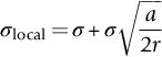
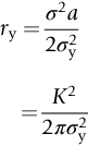
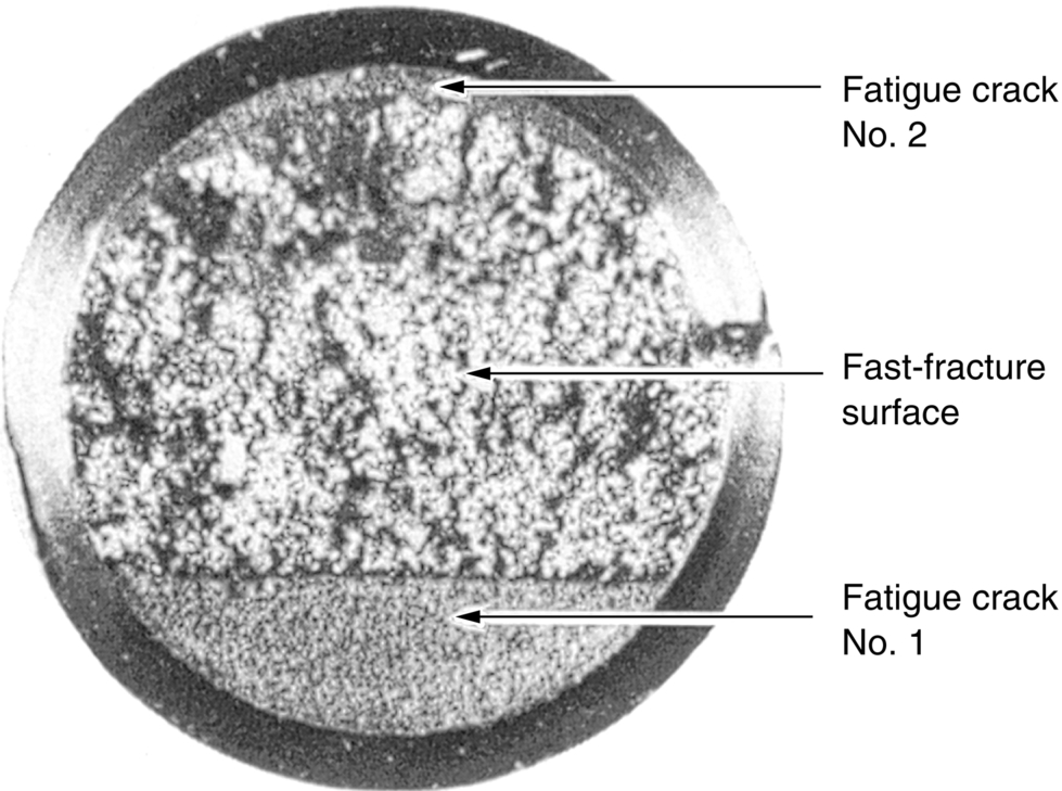
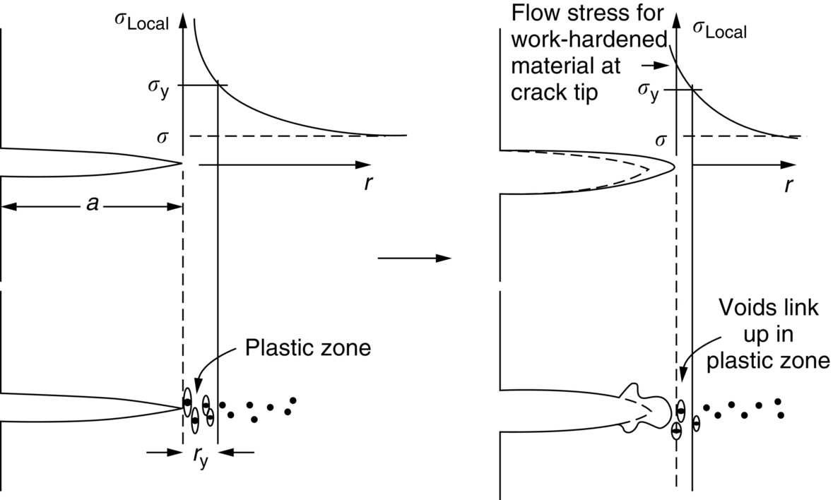
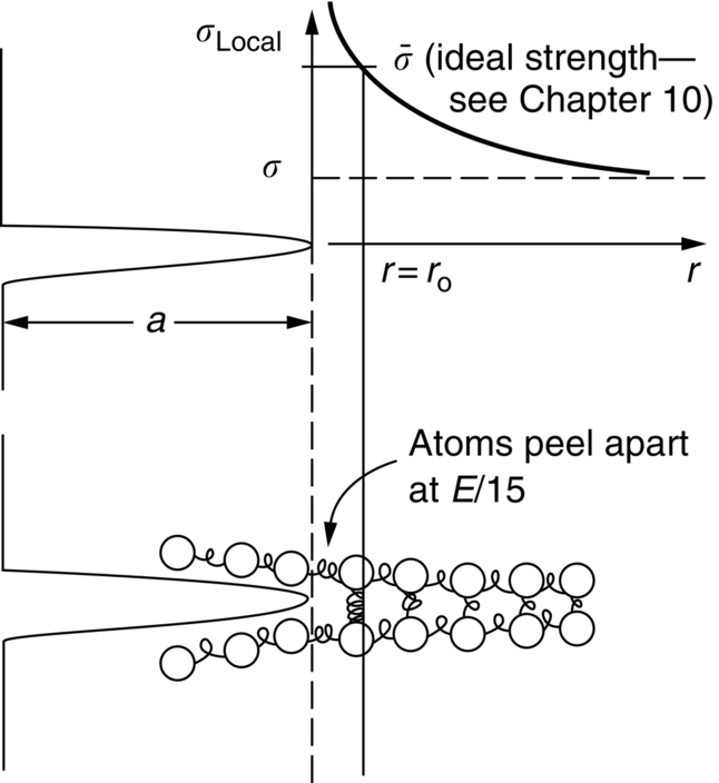
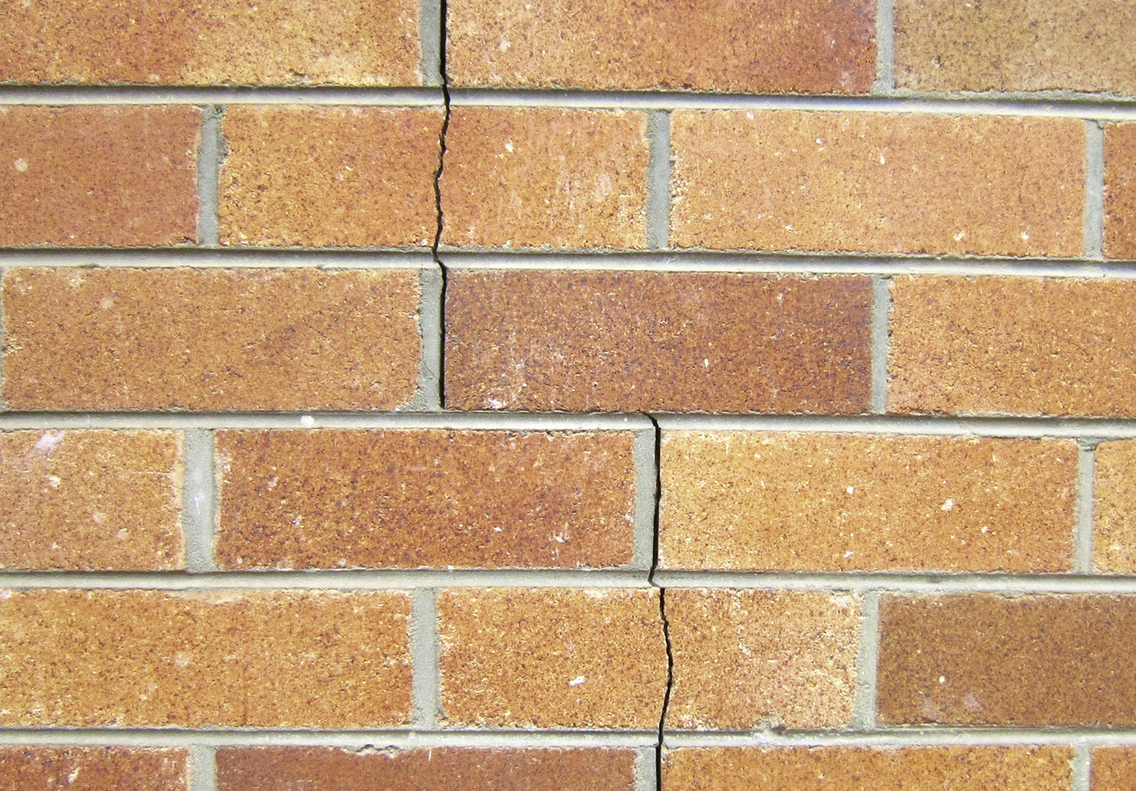
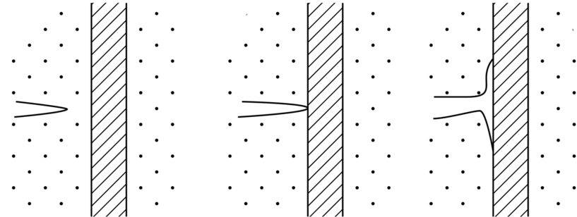
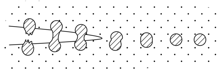
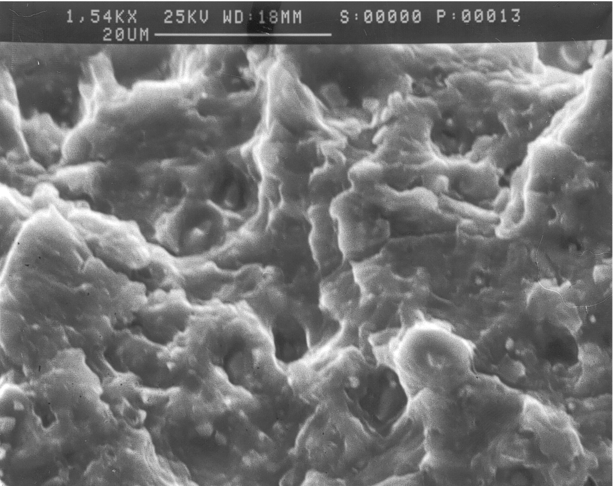
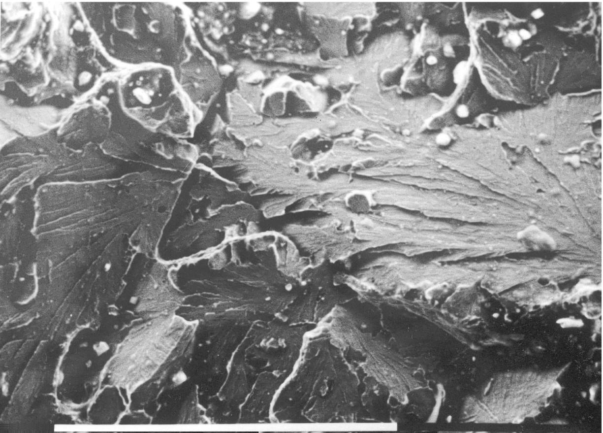
section epub:type=”chapter”> This chapter focuses on micromechanisms of fast fracture. The chapter discusses the mechanisms of crack propagation such as ductile tearing and cleavage. The chapter first takes a look at what happens when a cracked piece of a ductile metal is loaded —in other words, a metal that can flow readily to give large plastic deformations (e.g., pure copper; or mild steel at, or above, room temperature). If the material is sufficiently loaded, it can start to get fractured from the crack. If one examines the surfaces of the metal after it has fractured he will see that the fracture surface is extremely rough, indicating that a great deal of plastic work has taken place. Whenever a crack is present in a material, the stress close to the crack, σlocal, is greater than the average stress σ applied to the piece of material; the crack has the effect of concentrating the stress. The next section of this chapter discusses about composites, including wood. The low toughness of materials, such as epoxy resins or polyester resins, can be enormously increased by reinforcing them with carbon fiber or glass fiber. But why is it that putting a second, equally (or more) brittle material such as graphite or glass into a brittle polymer makes a tough composite? The reason is the fibers act as crack stoppers. This chapter concludes with a discussion of the way to avoid brittle alloys. In Chapter 14 we showed that, if a material contains a crack and is sufficiently stressed, the crack becomes unstable and grows—at up to the speed of sound in the material—to cause catastrophically rapid fracture, or fast fracture at a stress less than the yield stress. We were able to quantify this phenomenon and obtained a relationship for the onset of fast fracture or, in shorter notation, It is helpful to compare this with other, similar, failure criteria: The left side of each equation describes the loading conditions; the right side is a material property. When the left side (which increases with load) equals the right side (which is fixed), failure occurs. Some materials, such as glass, have low Kc, and crack easily; ductile metals have high Kc and are very resistant to fast-fracture; polymers have intermediate Kc, but can be made tougher by making them into composites; and (finally) many metals, when cold, become brittle—that is, Kc decreases with temperature. How can we explain these important observations? Let us first of all look at what happens when we load a cracked piece of a ductile metal—in other words, a metal that can flow readily to give large plastic deformations (e.g., pure copper; or mild steel at, or above, room temperature). If we load the material sufficiently, we can get fracture to take place starting from the crack. If you examine the surfaces of the metal after it has fractured (Figure 15.1) you see that the fracture surface is extremely rough, indicating that a great deal of plastic work has taken place. Let us explain this observation. Whenever a crack is present in a material, the stress close to the crack, σlocal, is greater than the average stress σ applied to the piece of material; the crack has the effect of concentrating the stress. Mathematical analysis shows that the local stress ahead of a sharp crack in an elastic material is The closer one approaches to the tip of the crack, the higher the local stress becomes, until at some distance ry from the tip of the crack the stress reaches the yield stress, σy of the material, and plastic flow occurs (Figure 15.2). The distance ry is easily calculated by setting σlocal = σy in Equation (15.1). Assuming ry to be small compared to the crack length, a, the result is The crack propagates when K is equal to Kc; the width of the plastic zone, ry, is then given by Equation (15.2) with K replaced by Kc. Note that the zone of plasticity shrinks rapidly as σy increases: cracks in soft metals have a large plastic zone; cracks in hard ceramics have a small zone, or none at all. Even when nominally pure, most metals contain tiny inclusions (or particles) of chemical compounds formed by reaction between the metal and impurity atoms. Within the plastic zone, plastic flow takes place around these inclusions, leading to elongated cavities, as shown in Figure 15.2. As plastic flow progresses, these cavities link up, and the crack advances by means of this ductile tearing. The plastic flow at the crack tip naturally turns our initially sharp crack into a blunt crack, and it turns out from the stress mathematics that this crack blunting decreases σlocal so that, at the crack tip itself, σlocal is just sufficient to keep on plastically deforming the work-hardened material there, as the figure shows. The important thing about crack growth by ductile tearing is that it consumes a lot of energy by plastic flow; the bigger the plastic zone, the more energy is absorbed. High energy absorption means that Gc is high, and so is Kc. This is why ductile metals are so tough. Other materials, too, owe their toughness to this behavior—plasticine is one, and some polymers also exhibit toughening by processes similar to ductile tearing. If you now examine the fracture surface of something like a ceramic, or a glass, you see a very different situation. Instead of a very rough surface, indicating massive local plastic deformation, you see rather flat surfaces, suggesting little or no plastic deformation. How is it that cracks in ceramics or glasses can spread without plastic flow taking place? Well, the local stress ahead of the crack tip, given by our formula can clearly approach very high values very near to the crack tip provided that blunting of our sharp crack tip does not occur. As we showed in Chapter 9, ceramics and glasses have very high yield strengths, and thus very little plastic deformation takes place at crack tips in these materials. Even allowing for a small degree of crack blunting, the local stress at the crack tip is still in excess of the ideal strength and is thus large enough to literally break apart the interatomic bonds there; the crack then spreads between a pair of atomic planes giving rise to an atomically flat surface by cleavage (Figure 15.3). The energy required simply to break the interatomic bonds is much less than that absorbed by ductile tearing in a tough material, and this is why materials like ceramics and glasses are so brittle (see Figure 15.4). It is also why some steels become brittle and fail, like glass, at low temperatures—as we shall now explain. At low temperatures metals having b.c.c. and c.p.h. structures become brittle and fail by cleavage, even though they may be tough at or above room temperature. In fact, only those metals with an f.c.c. structure (e.g., copper, lead, aluminum) remain unaffected by temperature in this way. In metals not having an f.c.c. structure, the motion of dislocations is assisted by the thermal agitation of the atoms (we shall talk in more detail about thermally activated processes in Chapter 22). At lower temperatures this thermal agitation is less, and the dislocations cannot move as easily as they can at room temperature in response to a stress—the intrinsic lattice resistance (Chapter 11) increases. The result is that the yield strength rises, and the plastic zone at the crack tip shrinks until it becomes so small that the fracture mechanism changes from ductile tearing to cleavage. This effect is called the ductile-to-brittle transition; for steels it can be as high as ≈0°C, depending on the composition of the steel; steel structures, such as ships, bridges, and oil rigs, are much more likely to fail in winter than in summer. A somewhat similar thing happens in many polymers at the glass–rubber transition that we mentioned in Chapter 6. Below the transition these polymers are much more brittle than above it, as you can easily demonstrate by cooling a piece of rubber or polyethylene in liquid nitrogen. (Many other polymers, such as epoxy resins, have low Kc values at all temperatures simply because they are heavily cross-linked at all temperatures by covalent bonds and the material does not flow at the crack tip to cause blunting.) As Figures 14.5 and 14.6 show, composites are tougher than ordinary polymers. The low toughness of materials, such as epoxy resins or polyester resins, can be enormously increased by reinforcing them with carbon fiber or glass fiber. But why is it that putting a second, equally (or more) brittle material such as graphite or glass into a brittle polymer makes a tough composite? The reason is the fibers act as crack stoppers (Figure 15.5). The sequence in the figure shows what happens when a crack runs through the brittle matrix toward a fiber. As the crack reaches the fiber, the stress field just ahead of the crack separates the matrix from the fiber over a small region (a process called debonding) and the crack is blunted so much that its motion is arrested. Naturally, this only works if the crack is running normal to the fibers: wood is very tough across the grain, but can be split easily (meaning that Kc is low) along it. One of the reasons why fiber composites are so useful in engineering design—in addition to their high stiffnesses that we talked about in Chapter 6—is their high toughness produced in this way. Of course, there are other ways of making polymers tough. The addition of small particles (“fillers”) of various sorts to polymers can modify their properties considerably. Rubber-toughened polymers (e.g., ABS), for example, derive their toughness from the small rubber particles they contain. A crack intersects and stretches them as shown in Figure 15.6. The particles act as little springs, clamping the crack shut, and thereby increasing the load needed to make it propagate. Let us finally return to the toughnesses of metals and alloys, as these are by far the most important class of materials for highly stressed applications. Even at, or above, room temperature, when nearly all common pure metals are tough, alloying of these metals with other metals or elements (e.g., with carbon to produce steels) can reduce the toughness. This is because alloying increases the resistance to dislocation motion (Chapter 11), raising the yield strength and causing the plastic zone to shrink. A more marked decrease in toughness can occur if enough impurities are added to make precipitates of chemical compounds formed between the metal and the impurities. These compounds can often be very brittle and, if they are present in the shape of extended plates (e.g., sigma-phase in stainless steel; graphite in cast iron), cracks can spread along the plates, leading to brittle fracture. Finally, heat-treatments of alloys such as steels can produce different crystal structures having great hardness (but also therefore great brittleness because crack blunting cannot occur). A good example of such a material is high-carbon steel after quenching into water from bright red heat: it becomes as brittle as glass. Proper heat treatment, following suppliers’ specifications, is essential if materials are to have the properties you want. Underground tunnels in deep coal mines are usually supported by mine arches, made from curved lengths of steel I-beam bolted together on site. At the mine arch factory, straight lengths of I-beam stock were stored outside in the open, and were brought into the factory for punching bolt holes, bending to curve, and cutting to length. Fractures were common when the bending process was carried out in cold weather (steel temperature ≤ 0°C). This was disruptive and expensive—the bending process had to be stopped, then the broken I-beam had to be removed from the bending machine, and scrapped. The following photographs show a typical fracture, from the edge of a punched hole, in the tensile part of the bending stress field. The fracture surface had the characteristics of a substantially brittle (cleavage) fracture: Once the first fracture occurred, further bending of the I-beam produced a tensile stress on the opposite side of the hole, which caused a second fracture. However, this fracture was a ductile shear fracture, with a fracture surface at 45° to the web surface (angle of maximum shear stress). These brittle fractures are an excellent example of the ductile-to-brittle transition in b.c.c. steels. The change from a ductile to a cleavage fracture mechanism was caused by a combination of: Both make it harder for plastic flow to occur, and the cleavage stress is now less than the yield stress.
Micromechanisms of Fast Fracture
Publisher Summary
15.1 Introduction
15.2 Mechanisms of Crack Propagation 1: Ductile Tearing
15.3 Mechanisms of Crack Propagation 2: Cleavage
15.4 Composites, Including Wood
15.5 Avoiding Brittle Alloys
Worked Example
Examples
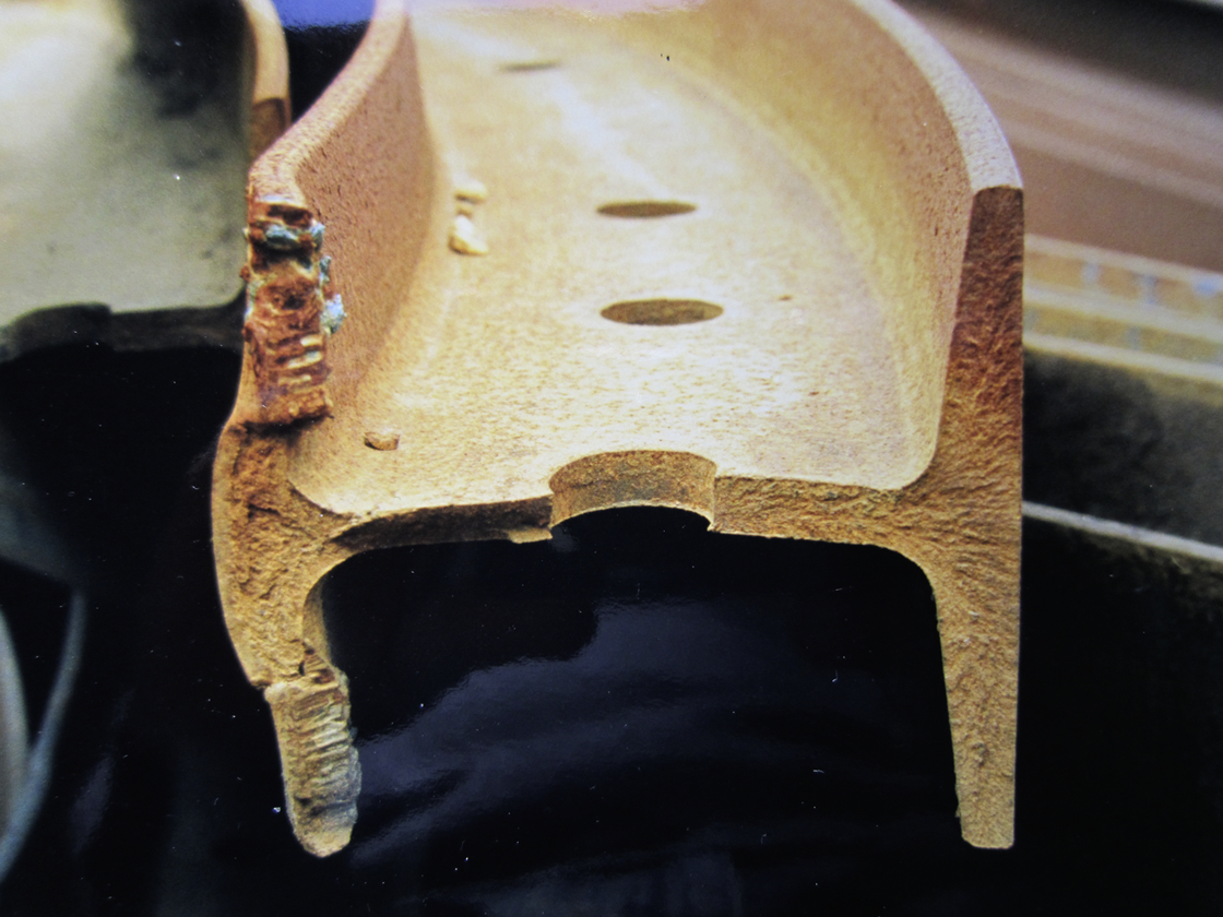
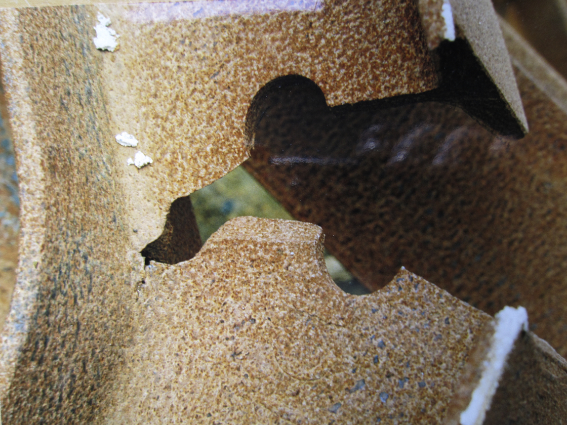
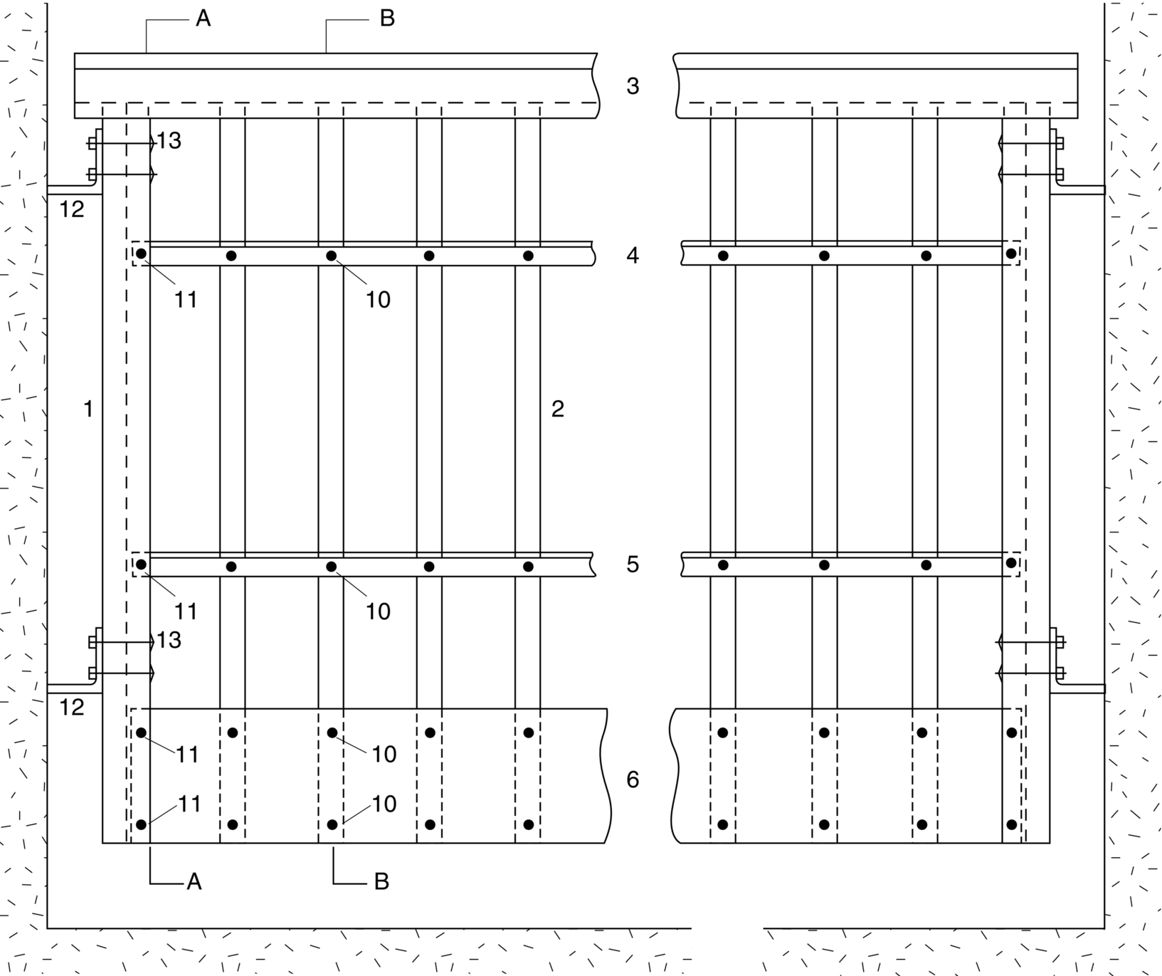
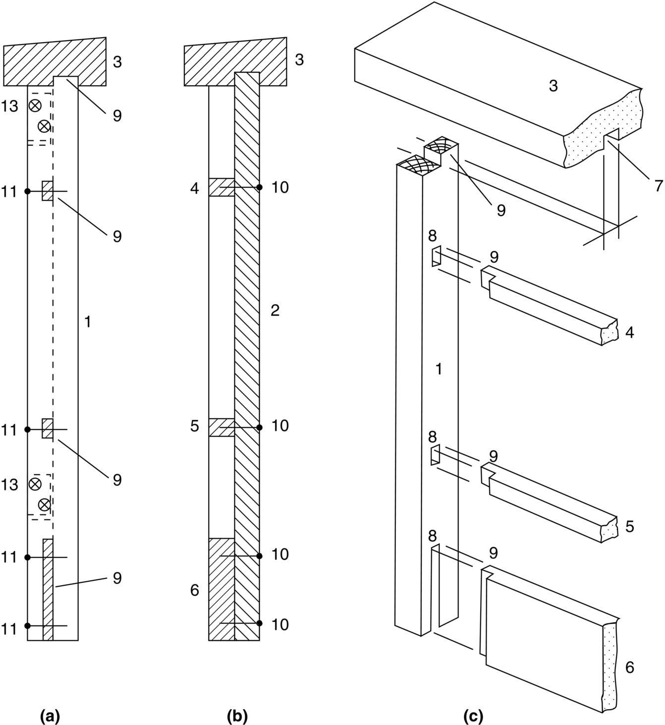
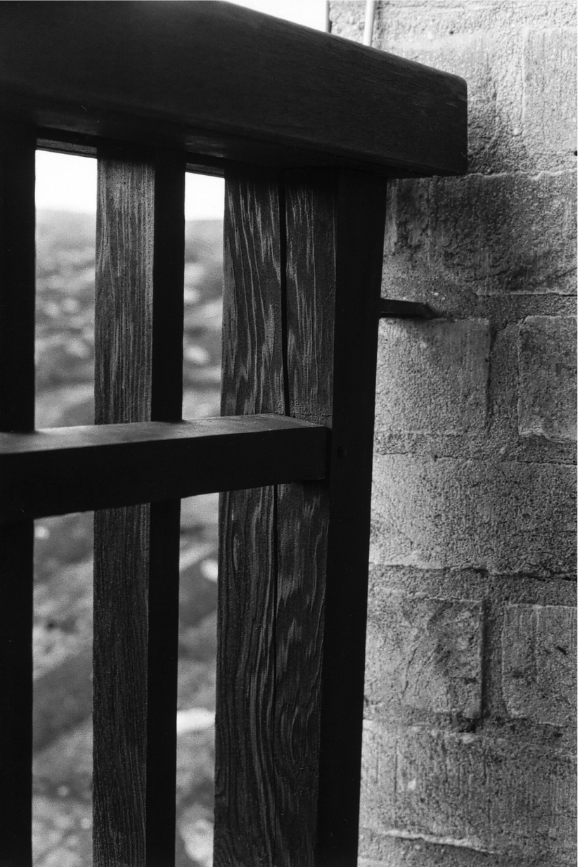
The diagrams on the next two pages show the design of the balustrades and a typical preexisting crack in a balustrade which has yet to fail (see photograph on page 242).
The numbers on the drawings are identified as follows: 1, end post (31-inch long); 2, baluster; 3, top rail (105-inch long); 4, top stringer; 5, bottom stringer; 6, kick board; 7, rebate groove; 8, blind mortise; 9, tenon; 10, 2-inch nail (head at outer face of baluster); 11, 2-inch nail (head at inner face of baluster); 12, galvanized steel fixing bracket cemented into brick wall; 13, steel coach screw ( -inch diameter).
Sketch the mode of failure, and account for it in terms of the fracture toughness of wood (numbers are not required).
You are called to a meeting with the architect. Explain to him or her the errors in the design, and how you think the balustrade should have been designed.
Answers
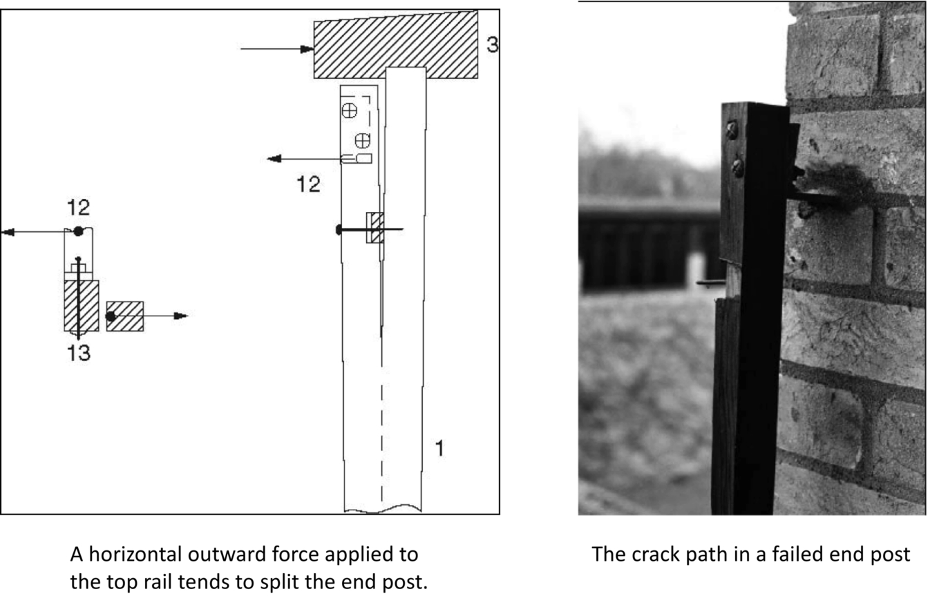
The collapse of the railing was caused by the propagation of pre-existing cracks in the end posts (1), which are safety-critical components. The crack path coincided with a sharp change of cross section in the end posts. The crack was opened up because the outward pressure on the top rail (3) was reacted by the fixing bracket (12). This would not have happened if the full width of the end post had been tenoned into the top rail. The problem was that only the outer half of the end post was tenoned into the top rail. The collapse was caused by the poor along-grain fracture toughness of wood, the source of crack-opening forces in the design, the tendency of externally exposed timber to develop cracks, and the significance of cracks for the integrity of the structure. You could recommend fixing the ends of the top rail directly to the brick wall, using a steel bracket bolted to both the top rail and the brick wall. This designs out the end posts and their problems entirely.
Disadvantages—Can split if nails or screws are driven in too close to the end or edge of a piece of wood. Need to drill pilot holes in hardwoods to avoid splitting. When wood dries out during seasoning, it shrinks across the grain, and the stresses this sets up can result in splitting along the grain.