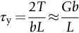
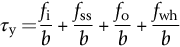
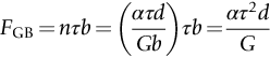
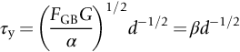
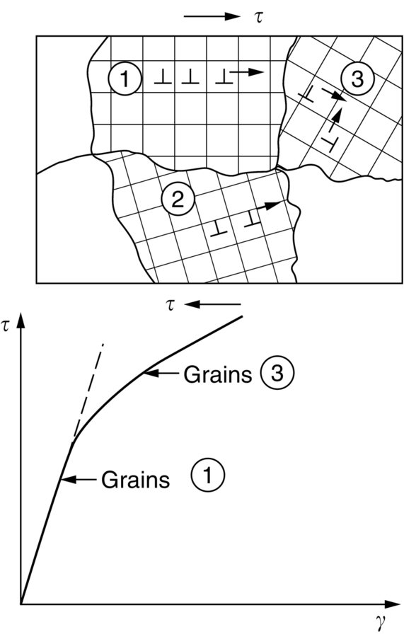
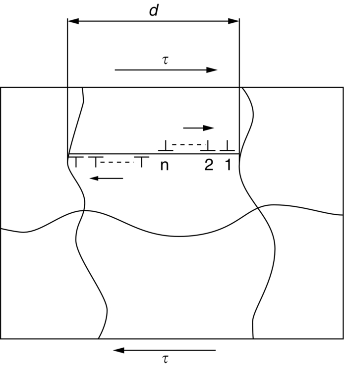
section epub:type=”chapter”> This chapter examines the ways of increasing the resistance to motion of a dislocation. Bulk engineering materials, however, are aggregates of many crystals or grains. To understand the plasticity of such an aggregate, the interaction of individual crystals with each other has to be examined. This allows to calculate the polycrystal yield strength—the quantity that enters engineering design. The chapter starts with a brief discussion of strengthening mechanisms. Most crystals have a certain intrinsic strength caused by the bonds between the atoms that have to be broken and reformed as the dislocation moves. A good way of hardening a metal is simply to make it impure. Impurities go into solution in a solid metal. A good example is the addition of zinc (Zn) to copper (Cu) to make the alloy called brass. If an impurity is dissolved in a metal or ceramic at a high temperature and the alloy is cooled to room temperature, the impurity may precipitate as small particles. The chapter concludes with a discussion of the dislocation yield strength. We showed in the last chapter that. In this chapter, we examine ways of increasing the resistance to motion of a dislocation—which determines the dislocation yield strength of a single isolated crystal of a metal or ceramic. Bulk engineering materials, however, are aggregates of many crystals, or grains. To understand the plasticity of such an aggregate, we also have to examine how the individual crystals interact with each other. This lets us calculate the polycrystal yield strength—the quantity that enters engineering design. A crystal yields when the force τb (per unit length) exceeds f, the resistance (force per unit length) opposing the motion of a dislocation. Using Equation (10.2) we can now define the dislocation yield strength Most crystals have a certain intrinsic strength, caused by the bonds between the atoms which have to be broken and reformed as the dislocation moves. Covalent bonding, particularly, gives a very large intrinsic lattice resistance, fi per unit length of dislocation. It is this that causes the enormous strength and hardness of diamond, and the carbides, oxides, nitrides, and silicates that are used for abrasives and cutting tools. But pure metals are very soft: they have a very low lattice resistance. Then it is useful to increase f by solid solution strengthening, by precipitate or dispersion strengthening, or by work-hardening, or by any combination of the three. Remember, however, that there is an upper limit to the yield strength: it can never exceed the ideal strength. In practice, only a few materials have strengths that even approach it. A good way of hardening a metal is simply to make it impure. Impurities go into solution in a solid metal just as sugar dissolves in coffee. A good example is the addition of zinc (Zn) to copper (Cu) to make the alloy called brass. The zinc atoms replace copper atoms to form a random substitutional solid solution. At room temperature Cu will dissolve up to 30% Zn in this way. The Zn atoms are bigger than the Cu atoms, and, in squeezing into the Cu structure, generate stresses. These stresses “roughen” the slip plane, making it harder for dislocations to move; they increase the resistance f, and thereby increase the dislocation yield strength, τy (Equation (11.1)). If the contribution to f given by the solid solution is fss then τy is increased by fss/b. In a solid solution of concentration C, the spacing of dissolved atoms on the slip plane varies as C–1/2; and the smaller the spacing, the “rougher” is the slip plane. As a result, τy increases parabolically (i.e., as C1/2) with solute concentration (Figure 11.1). Single-phase brass, bronze, and stainless steels, as well as many other metallic alloys, derive their strength in this way. If an impurity is dissolved in a metal or ceramic at a high temperature, and the alloy is cooled to room temperature, the impurity may precipitate as small particles, much as sugar will crystallize from a saturated solution when it is cooled. An alloy of Al containing 4% Cu (“Duralumin”) treated in this way gives small, closely spaced precipitates of the hard compound CuAl2. Most steels are strengthened by precipitates of carbides. Small particles can be introduced into metals or ceramics in other ways. The most obvious is to mix a dispersoid (such as an oxide) into a powdered metal (aluminum and lead are both treated in this way), and then compact and sinter the mixed powders. Either approach distributes small, hard particles in the path of a moving dislocation. Figure 11.2 shows how they obstruct its motion. The stress τ has to push the dislocation between the obstacles. It is like blowing up a balloon in a bird cage: a very large pressure is needed to bulge the balloon between the bars, though once a large enough bulge is formed, it can easily expand further. The critical configuration is the semicircular one (Figure 11.2(c)): here the force τbL on one segment is just balanced by the force 2T due to the line tension, acting on either side of the bulge. The dislocation escapes (and yielding occurs) when (Remember that The obstacles thus exert a resistance of f0 = 2T/L. Obviously, the greatest hardening is produced by strong, closely spaced precipitates or dispersions (Figure 11.2). When crystals yield, dislocations move through them. Most crystals have several slip planes: the f.c.c. structure, which slips on {111} planes, has four, for example. Dislocations on these intersecting planes interact, and obstruct each other, and accumulate in the material. The result is work-hardening: the steeply rising stress–strain curve after yield, shown in Chapter 9. All metals work-harden. It can be a nuisance: if you want to roll thin sheet, work-hardening quickly raises the yield strength so much that you have to stop and anneal the metal (heat it up to remove the accumulated dislocations) before you can go on. But it is also useful—it is a potent strengthening method, which can be added to the other methods to produce strong materials. The analysis of work-hardening is complex. Its contribution fwh to the total dislocation resistance f is considerable and increases with strain (Figure 11.3). It is adequate to assume that the strengthening methods contribute in an additive way to the strength. Then Strong materials either have a high intrinsic strength, fi (e.g., diamond), or they rely on the superposition of solid solution strengthening fss, obstacles fo, and work-hardening fwh (e.g., high-tensile steels). But before we can use this information, one problem remains: we have calculated the yield strength of an isolated crystal in shear. We want the yield strength of a polycrystalline aggregate in tension. The crystals, or grains, in a polycrystal fit together exactly but their crystal orientations differ (Figure 11.4). Where they meet, at grain boundaries, the crystal structure is disturbed, but the atomic bonds across the boundary are numerous and strong enough that the boundaries do not usually weaken the material. Let us now look at what happens when a polycrystalline component begins to yield (Figure 11.5). Slip begins in grains where there are slip planes as nearly parallel to τ as possible, for example, grain (1). Slip later spreads to grains like (2) which are not so favorably oriented, and lastly to the worst oriented grains like (3). Yielding does not take place all at once, therefore, and there is no sharp polycrystalline yield point on the stress–strain curve. Further, gross (total) yielding does not occur at the dislocation yield strength τy, because not all the grains are oriented favorably for yielding. The gross yield strength is higher, by a factor called the Taylor factor, which is calculated (with difficulty) by averaging the stress over all possible slip planes—it is close to 1.5. But we want the tensile yield strength, σy. A tensile stress σ creates a shear stress in the material that has a maximum value of τ = σ/2. (We show this in Chapter 12 where we resolve the tensile stress onto planes within the material.) To calculate σy from τy, we combine the Taylor factor with the resolution factor to give σy is the quantity we want: the yield strength of bulk, polycrystalline solids. It is larger than the dislocation yield strength τy (by the factor 3) but is proportional to it. So all the statements we have made about increasing τy apply unchanged to σy. The presence of grain boundaries in a polycrystalline material has an additional consequence—they contribute to the yield strength because grain boundaries act as obstacles to dislocation movement. Because of this, dislocations pile up against grain boundaries, as shown in Figure 11.6. The number of dislocations that can form in a pile-up is given by where α is a constant and d is the grain size. If there were only one dislocation piled-up against the grain boundary, the force on it would be f = τb, as shown in Equation (10.2). However, in a pile-up of n dislocations, each dislocation exerts a force on the one in front, so the force on the leading (number 1) dislocation is nτb. If this force exceeds a critical value, FGB, then the leading dislocation will move through the grain boundary, and yield will occur. The yield condition is given by The contribution to the dislocation yield strength τy is therefore where β is a constant. The interesting consequence of this result is that fine-grained materials (large d–1/2) have a higher yield strength than coarse-grained materials (small d–1/2). However, the value of β is specific to the material, and is less for some alloys than others. A whole science of alloy design for high strength has grown up in which alloys are blended and heat-treated to achieve maximum τy. Important components that are strengthened in this way range from lathe tools (“high-speed” steels) to turbine blades (“Nimonic” alloys based on nickel). We shall have more to say about strong solids when we come to look at how materials are selected for a particular application.
Strengthening and Plasticity of Polycrystals
Publisher Summary
11.1 Introduction
11.2 Strengthening Mechanisms
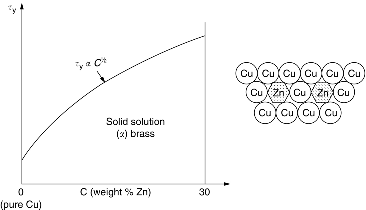
11.3 Solid Solution Hardening
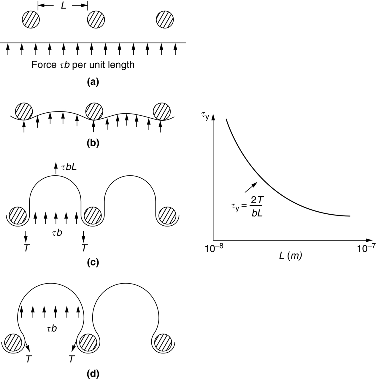
11.4 Precipitate and Dispersion Strengthening
 , from Equation (10.3).)
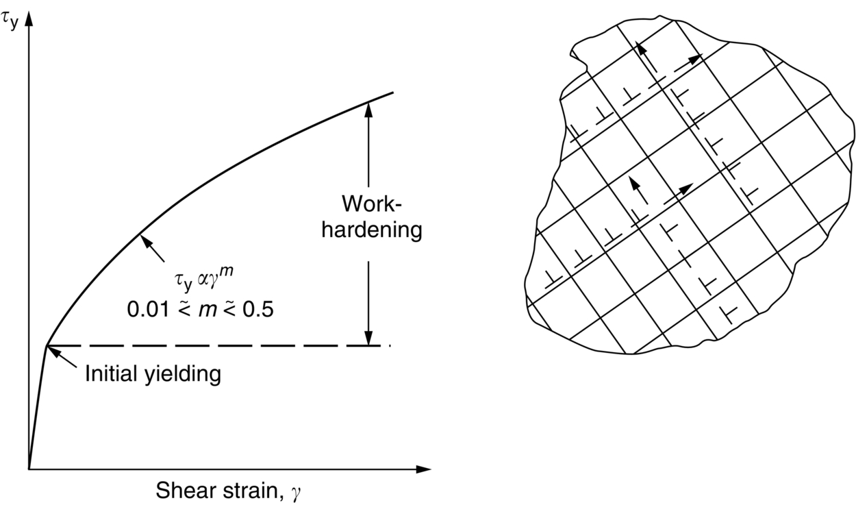
11.5 Work-Hardening
11.6 Dislocation Yield Strength
11.7 Yield in Polycrystals
Grain-boundary strengthening (Hall–Petch effect)
11.8 Final Remarks
Examples
Answers