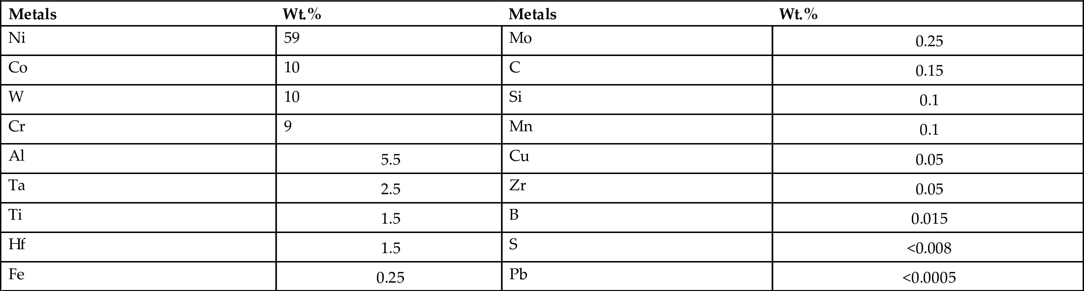
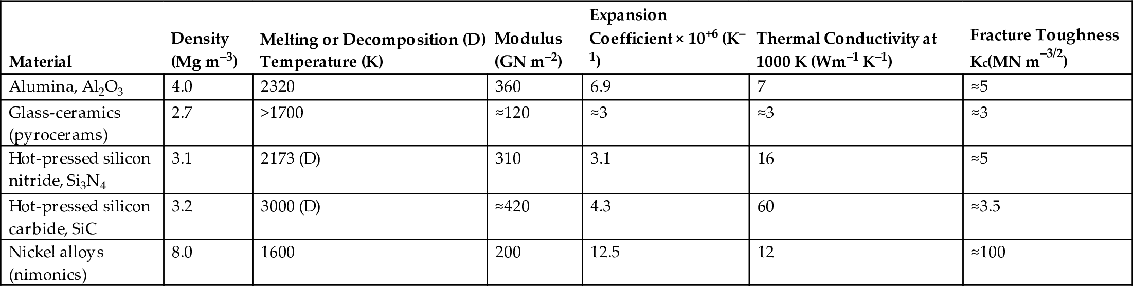
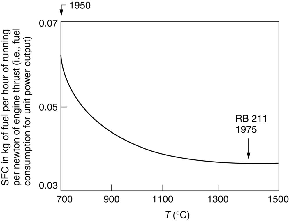
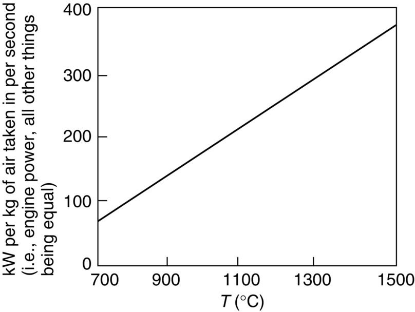
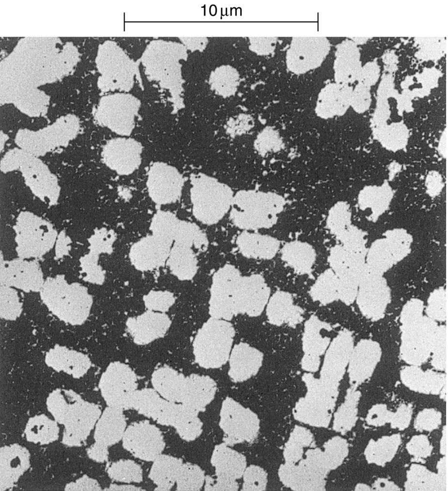
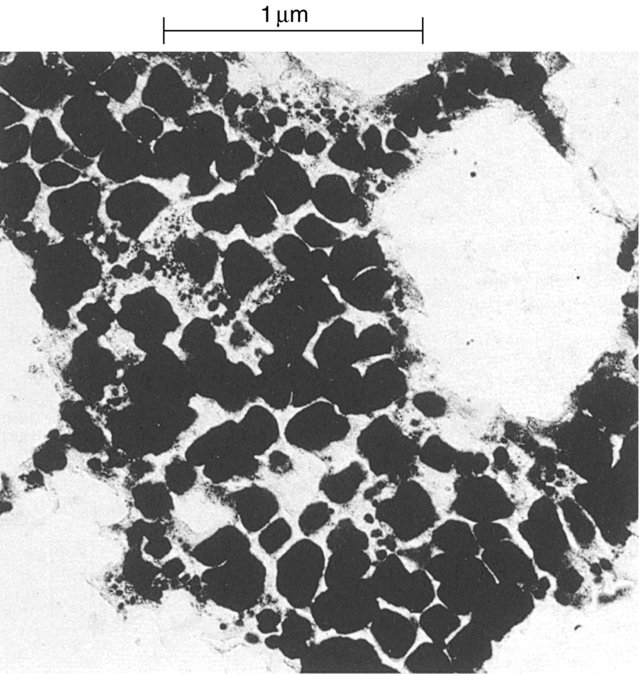
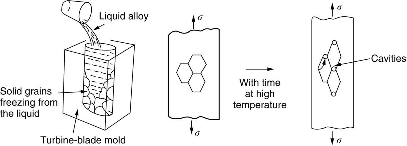
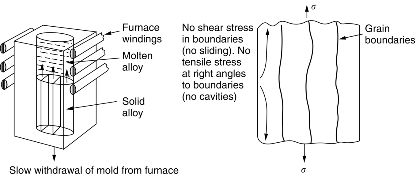
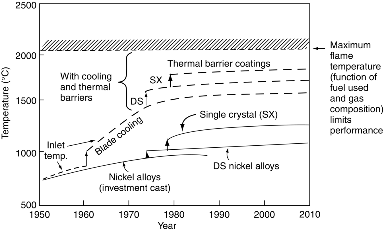
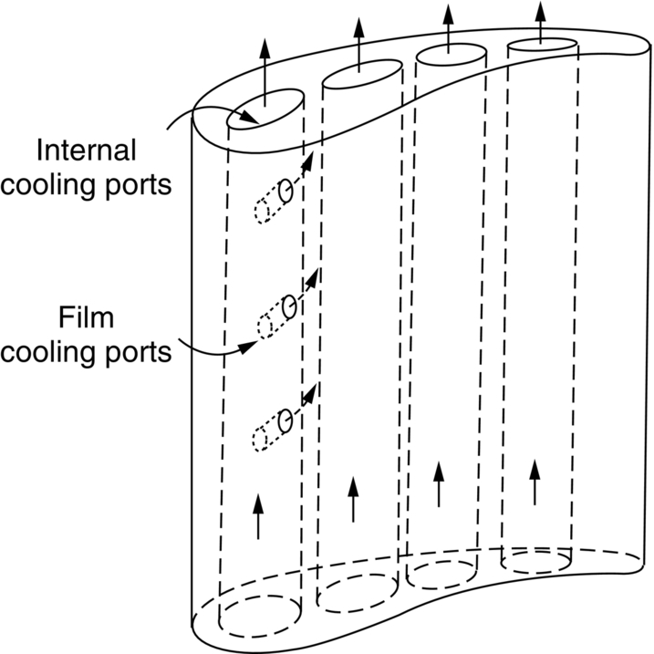
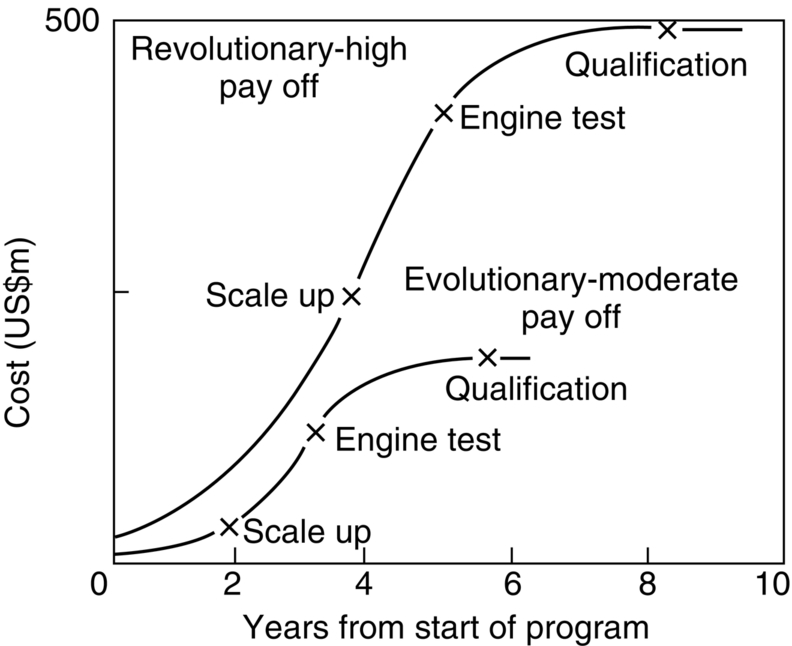
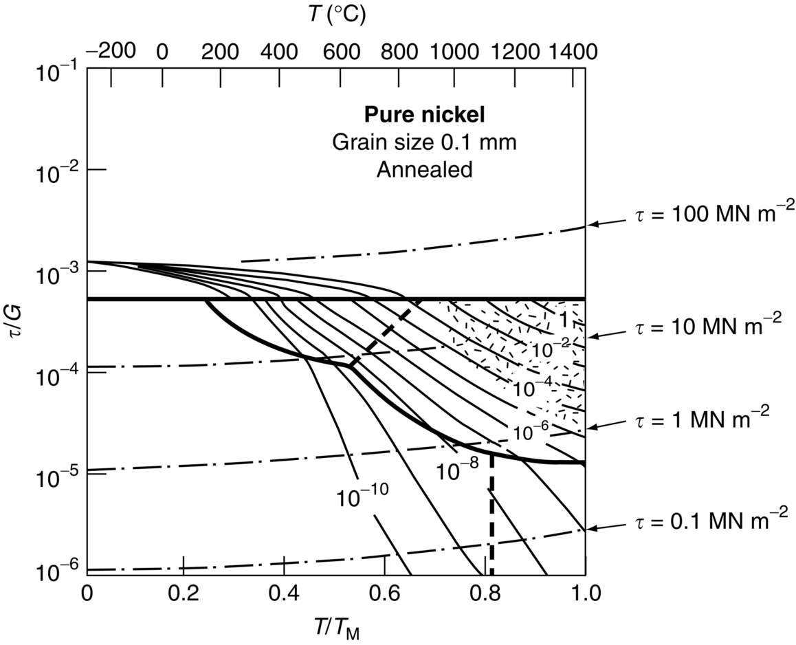
section epub:type=”chapter”> It has been seen how a basic knowledge of the mechanisms of creep was an important aid to the development of materials with good creep properties. An impressive example is in the development of materials for the high-pressure stage of a modern aircraft gas turbine. This chapter examines the properties that such materials must have, the way in which the present generation of materials has evolved, and the likely direction of their future development. In 1950, a typical aeroengine operated at 700°C. The incentive then to increase the inlet temperature was strong because of the steepness of the fuel-consumption curve at that temperature. By 1975, a typical engine (the RB211, for instance) operated at 1350°C with a 50% saving in fuel per unit power output over the 1950 engines. This chapter begins with the discussion of properties required of a turbine blade. The alloy used for turbine blades in the high-pressure stage of an aircraft turbofan engine is a classic example of a material designed to be resistant to dislocation (power-law) creep at high stresses and temperatures. The chapter focuses on engineering developments, more specifically, of blade cooling and future developments of the ceramics best suited for structural use at high temperatures. This chapter concludes with a discussion of the cost effectiveness of turbine blades. In the last chapter we saw how a basic knowledge of the mechanisms of creep was an important aid to the development of materials with good creep properties. An impressive example is in the development of materials for the high-pressure stage of a modern aircraft gas turbine (see Figure 1.3). Here we examine the properties such materials must have, the way in which the present generation of materials has evolved, and the likely direction of their future development. The ideal thermodynamic efficiency of a heat engine is given by where T1 and T2 are the absolute temperatures of the heat source and heat sink respectively. Obviously the greater T1, the greater the maximum efficiency that can be derived from the engine. In practice the efficiency is a good deal less than ideal, but an increase in combustion temperature in a turbofan engine will, nevertheless, generate an increase in engine efficiency. Figure 24.1 shows the variation in efficiency of a turbofan engine plotted as a function of the turbine inlet temperature. In 1950 a typical aeroengine operated at 700°C. The incentive then to increase the inlet temperature was strong, because of the steepness of the fuel-consumption curve at that temperature. By 1975 a typical engine (the RB211, for instance) operated at 1350°C, with a 50% saving in fuel per unit power output over the 1950 engines. But is it worth raising the temperature further? The shallowness of the consumption curve at 1400°C suggests that it might not be profitable; but there is a second factor: power-to-weight ratio. Figure 24.2 shows a typical plot of the power output of a particular engine against turbine inlet temperature. This increases linearly with the temperature. If the turbine could both run at a higher temperature and be made of a lighter material there would be a double gain, with important financial benefits of increased payload. Let us first examine the development of turbine-blade materials to meet the challenge of increasing engine temperatures. Although so far we have been stressing the need for excellent creep properties, a turbine-blade alloy must satisfy other criteria too. They are listed in Table 24.1. Table 24.1 The first—creep—is our interest here. The second—resistance to oxidation—is the subject of Chapter 25. Toughness and fatigue resistance (Chapters 14 and 18) are obviously important: blades must be tough enough to withstand the impact of birds and hailstones; and changes in the power level of the engine produce mechanical and thermal stresses which—if the blade material is wrongly chosen—cause thermal fatigue. The alloy composition and structure must remain stable at high temperature—precipitate particles can dissolve away if the alloy is overheated and the creep properties will then degrade significantly. Finally, the density must be as low as possible—not so much because of blade weight but because of the need for stronger and hence heavier turbine discs to take the radial load. These requirements severely limit our choice of creep-resistant materials. For example, ceramics, with their high softening temperatures and low densities, are ruled out for aeroengines because they are far too brittle (they are under evaluation for use in land-based turbines, where the risks and consequences of sudden failure are less severe—see the following). Cermets offer no great advantage because their metallic matrices soften at much too low a temperature. The materials that best fill present needs are the nickel-based super-alloys. The alloy used for turbine blades in the high-pressure stage of an aircraft turbofan engine is a classic example of a material designed to be resistant to dislocation (power-law) creep at high stresses and temperatures. At take-off, the blade is subjected to stresses approaching 250 MN m–2, and the design specification requires that this stress shall be supported for 30 h at 850°C without more than a 0.1% irreversible creep strain. In order to meet these stringent requirements, an alloy based on nickel has evolved with the rather mind-blowing specification given in Table 24.2. No one tries to remember exact details of this or similar alloys. But the point of all these complicated additions of foreign atoms to the nickel is straightforward. It is: (a) to have as many atoms in solid solution as possible (the cobalt, the tungsten, and the chromium); (b) to form stable, hard precipitates of compounds such as Ni3Al, Ni3Ti, MoC, TaC to obstruct the dislocations; and (c) to form a protective surface oxide film of Cr2O3 to protect the blade itself from attack by oxygen (we shall discuss this in Chapter 26). Figure 24.3(a, b) shows a piece of a nickel-based super-alloy cut open to reveal its complicated structure. These super-alloys are remarkable materials. They resist creep so well that they can be used at 850°C—and since they melt at 1280°C, this is 0.72 of their (absolute) melting point. They are so hard that they cannot be machined easily by normal methods, and must be precision-cast to their final shape. This is done by investment casting: a precise wax model of the blade is embedded in an alumina paste which is then fired; the wax burns out leaving an accurate mold from which one blade can be made by pouring liquid super-alloy into it (Figure 24.4). Cast in this way, the grain size of such a blade is small (Figure 24.4). The strengthening caused by alloying successfully suppresses power-law creep, but at 0.72TM, diffusional flow then becomes a problem. The way out is to increase the grain size, or even make single-crystal blades with no grain boundaries at all. In addition, creep damage (Chapter 23) accumulates at grain boundaries; we can obviously delay failure by eliminating grain boundaries, or aligning them parallel to the applied stress. To do this, we directionally solidify the alloys (see Figure 24.5) to give long grains with grain boundaries parallel to the applied stress (or single-crystal blades with no grain boundaries). The diffusional distances required for diffusional creep are then very large (greatly cutting down the rate of diffusional creep); in addition, there is no driving force for grain-boundary sliding or for cavitation at grain boundaries. Directionally solidified (DS) and single crystal (SX) alloys are standard in all high-performance engines. The improved creep properties of these alloys allows the engine to run at a flame temperature approximately 200°C higher than before. How was this type of alloy discovered in the first place? Well, the fundamental principles of creep-resistant materials design that we talked about help us to select the more promising alloy recipes and discard the less promising ones fairly easily. Thereafter, the approach is an empirical one. Alloys having different recipes are made up in the laboratory and tested for creep, oxidation, toughness, thermal fatigue, and stability. The choice eventually narrows down to a few and these are subjected to more stringent testing, coupled with judicious tinkering with the alloy recipe. Small improvements are continually made in alloy composition and in the manufacture of finished blades, which evolve by a sort of creepy Darwinism, the fittest (in the sense of Table 24.1) surviving. Figure 24.6 shows how this evolutionary process has resulted in a continual improvement of creep properties of nickel alloys over time. The figure also shows how improvements in alloy manufacture—directional solidification and growing single crystals—have helped to increase the operating temperature. Nevertheless, it is clear from the graph that improvements in nickel alloys are now nearing the point of diminishing returns. Figure 24.6 shows that up until 1960 turbine inlet temperatures were virtually the same as the metal temperatures. After 1960 there was a sharp divergence, with inlet temperatures substantially above the temperatures of the blade metal itself—indeed, the gas temperature is greater than the melting point of the blades. Impossible? Not at all. It is done by air-cooling the blades, and in a cunning way. In the earliest form of cooled blade, cooling air from the compressor stage of the engine was fed through ports passing along the full length of the blade, and was ejected into the gas stream at the blade end (see Figure 24.7). This internal cooling of the blade enabled the inlet temperature to be increased immediately by 100°C with no change in alloy composition. A later improvement was film cooling, in which the air was ejected over the surface of the blade, through little holes connected to the central channel, giving a cool boundary layer between the blade and the hot gases. More recently, blades have been coated with thin layers of ceramics—such as zirconium oxide (zirconia). These protect the blades from oxidation and hot corrosion, but because they are also poor conductors of heat, they add a thin layer of thermal insulation between the hot gases and the metal of the blade—they are “thermal barrier coatings.” A program of continuous improvement in the efficiency of heat transfer by refinements of this type has made it possible for modern turbofans to operate at temperatures that are no longer dominated by the properties of the material. But blade cooling has reached a limit: ducting still more cold air through the blades will begin to reduce the thermal efficiency by taking too much heat away from the combustion chamber. What do we do now? The ceramics best suited for structural use at high temperatures (>1000°C) are listed in Table 24.3 and compared with nickel-based super-alloys. The comparison shows that all the ceramics have attractively low densities, high moduli, and high melting points (and thus excellent creep strength at 1000°C); and many are completely resistant to oxidation—they are oxides already. But several have poor thermal conductivity (leading to high thermal stresses) and all have very low toughness. Alumina (Al2O3) was one of the first pure oxides to be produced in complex shapes, but its combination of high expansion coefficient, poor conductivity, and low toughness gives it bad thermal-shock resistance. Glass ceramics are made by forming a complex silicate glass and then causing it to crystallize partly. They are widely used for ovenware and for heat exchangers for small engines. Their low thermal expansion gives them much better thermal shock resistance than most other ceramics, but the upper working temperature of 900°C (when the glass phase softens) limits their use. The covalently-bonded silicon carbide, silicon nitride, and sialons (alloys of Si3N4 and Al2O3) seem to be the best bet for high-temperature structural use. Their creep resistance is outstanding up to 1300°C, and their low expansion and high conductivity (better than nickel alloys!) reduces thermal stress. They can be formed by hot-pressing fine powders, by vapor deposition, or by nitriding silicon which is already pressed to shape: in this way, precise shapes (e.g., turbine blades) can be formed without the need for machining (they are much too hard to machine). Their brittleness, however, creates major design problems. It might be overcome by creating ceramics with a fibrous structure. In an effort to do this, ceramic-matrix components are under development: they combine strong, exceptionally perfect, fibers (e.g., silicon carbide or alumina, grown by special techniques) in a matrix of ceramic (silicon carbide or alumina again). Any major materials development program, such as that on DS/SX super-alloys, can only be undertaken if a successful outcome would be cost effective. As Figure 24.8 shows, the costs of development can be colossal. Even before a new material is out of the laboratory, $200 million can have been spent, and failure in an engine test can be expensive. Because the performance of a new alloy cannot finally be verified until it has been extensively flight-tested, at each stage of development risk decisions have to be taken whether to press ahead, or cut losses and abandon the program. One must consider, too, the cost of the materials themselves. Some of the metals used in conventional nickel alloys—such as hafnium—are hideously expensive and extremely scarce; and the use of greater and greater quantities of exotic materials in an attempt to improve the creep properties will drive the cost up. A single-crystal turbine blade currently costs US$10,000, so a set of blades for a high-pressure turbine disc typically runs to US$1 million! But expensive though it is, the cost of the turbine blades is still only a fraction of the cost of an engine, or of the fuel it will consume in its lifetime. Blade costs are important, but if new alloys offer improved life or inlet temperature, there is a strong incentive to pursue them. The diagrams that follow show deformation-mechanism maps for pure nickel and a nickel-based superalloy (MAR–M200), both having a grain size of 0.1 mm. The effect of the alloying additions in the superalloy (solid solution and precipitate strengthening) is dramatic—the yield stress is increased by more than 10 times, and the field of power-law creep is reduced to a small zone at the top right corner of the diagram. At 1000°C, the bottom of the power-law creep field is situated at a shear stress of 1 MN m–2 for nickel, but 100 MN m–2 for the superalloy—a factor of 100 times higher in stress. The result is that the creep of the superalloy in a gas turbine application is governed by diffusion creep. However, with a grain size as small as 0.1 mm, the creep rates are far too high. At a shear stress of 10 MN m–2 and 1000°C, the shear strain rate is 10–7 s–1—in one year of operation, this would give a creep strain of 100%! Since the creep rate scales as 1/d2 (Equation 23.2), increasing the grain size to 1 mm would decrease the strain rate by 100 times. This would give a creep strain of 1%—better, but still not good enough. This is why it is so important for hot-end applications to have a large grain size—or no grain size at all (SX). A 5 mm grain size (effectively through the thickness of the blade) would decrease the strain rate by 2500 times—to 0.04% per year, which is OK. Using DS or SX blades would suppress diffusion creep even more, and might allow the blade to be run at a higher stress.
The Turbine Blade—A Case Study in Creep-Limited Design
Publisher Summary
24.1 Introduction
24.2 Properties Required of a Turbine Blade
Criteria
Resistance to creep
Resistance to high-temperature oxidation
Toughness
Thermal fatigue resistance
Thermal stability
Low density
24.3 Nickel-Based Super-Alloys
24.4 Engineering Developments—Blade Cooling
24.5 Future Developments: High-Temperature Ceramics
24.6 Cost Effectiveness
Worked Example

Examples
Answers