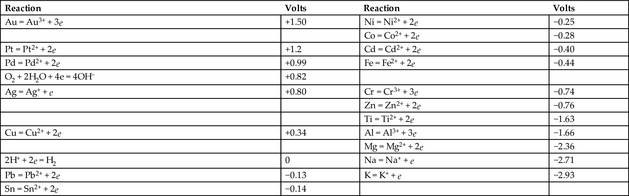
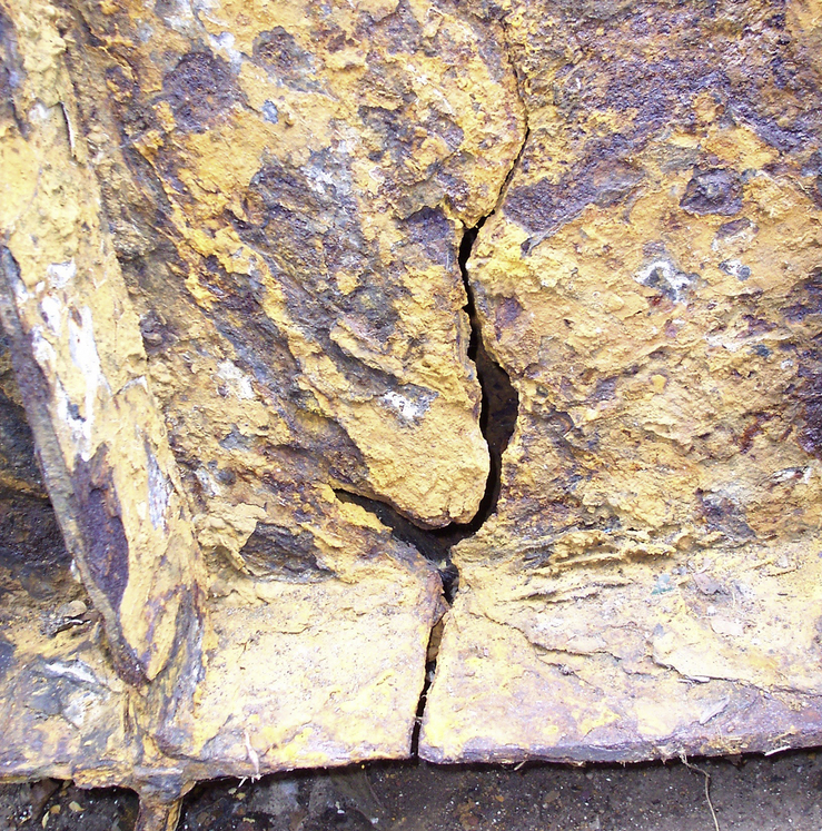
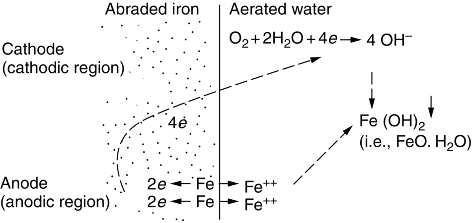
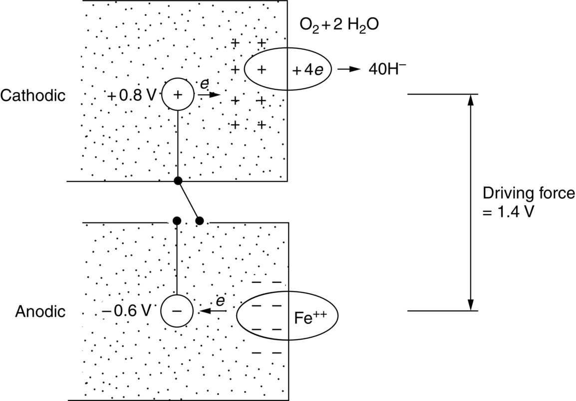
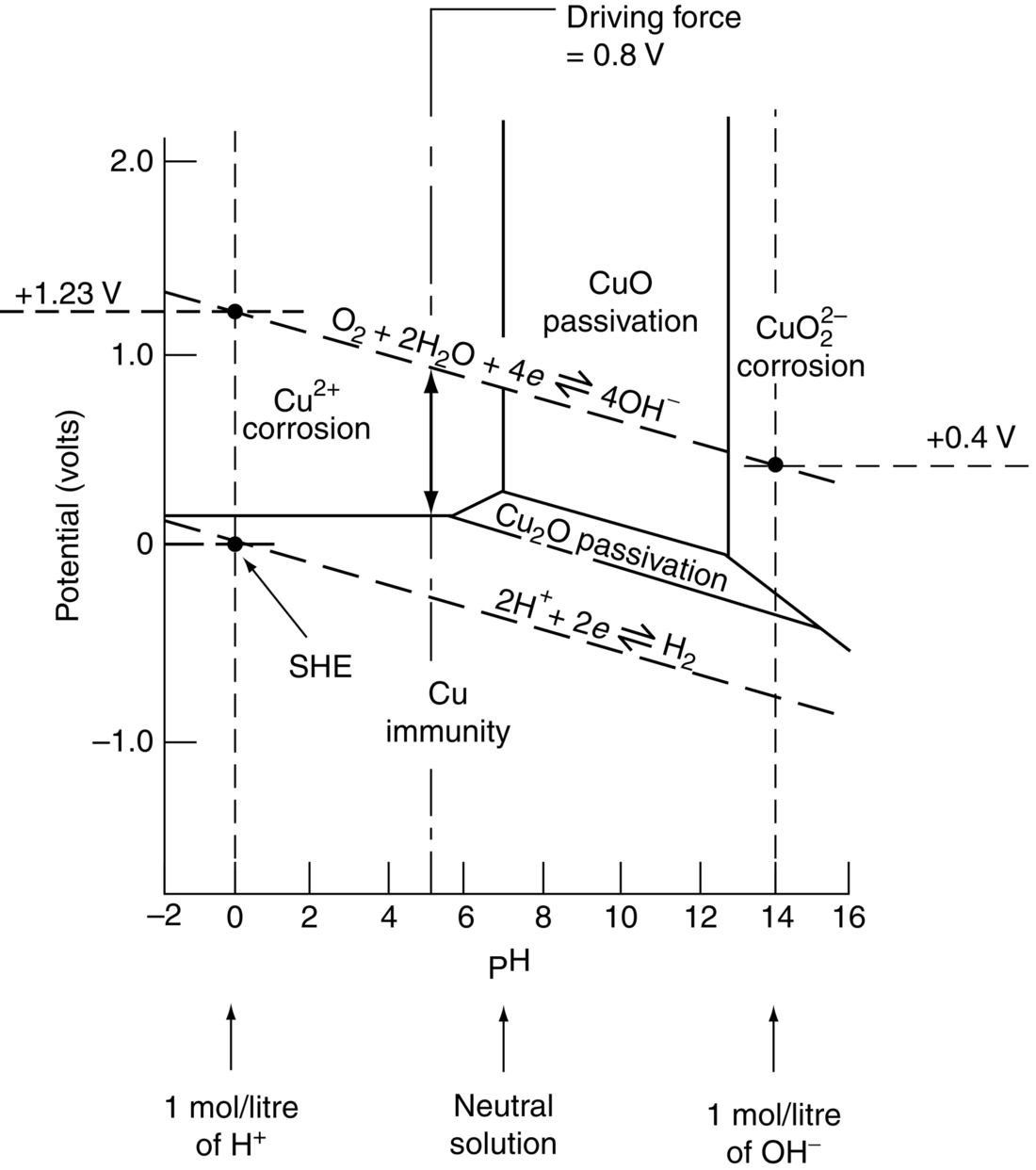
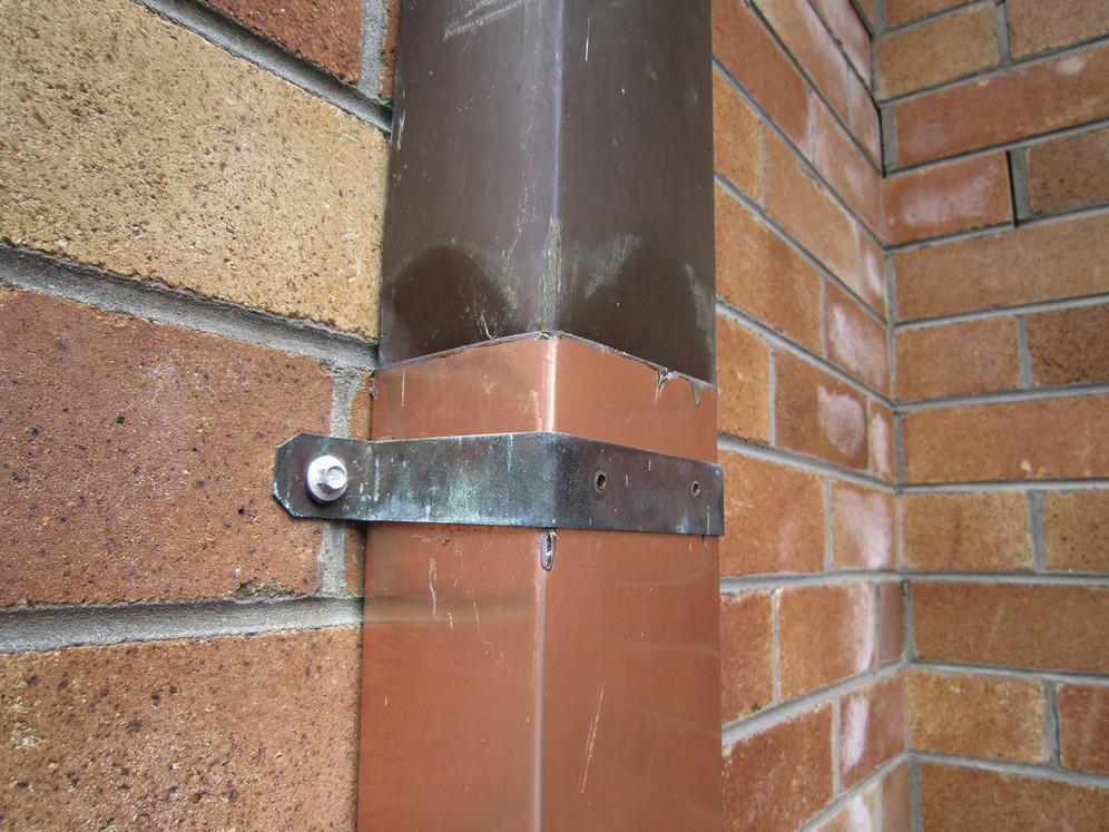
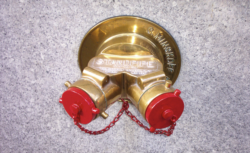
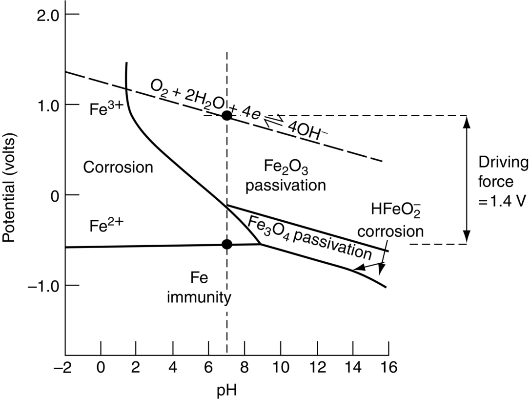
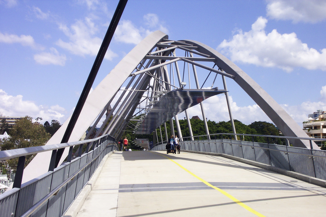
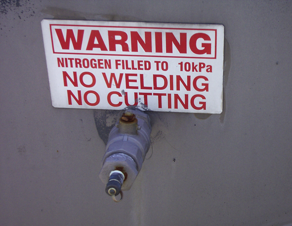
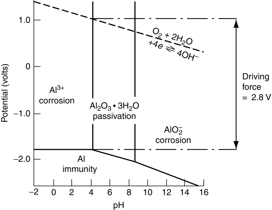
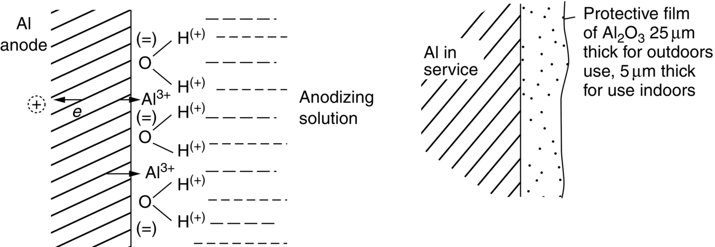
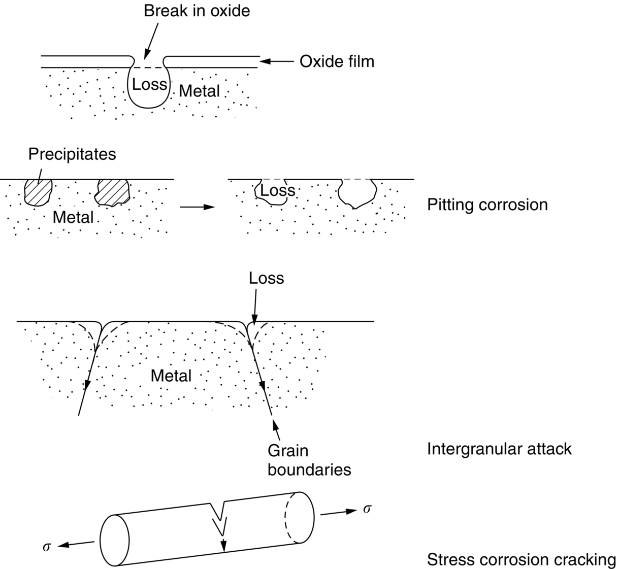
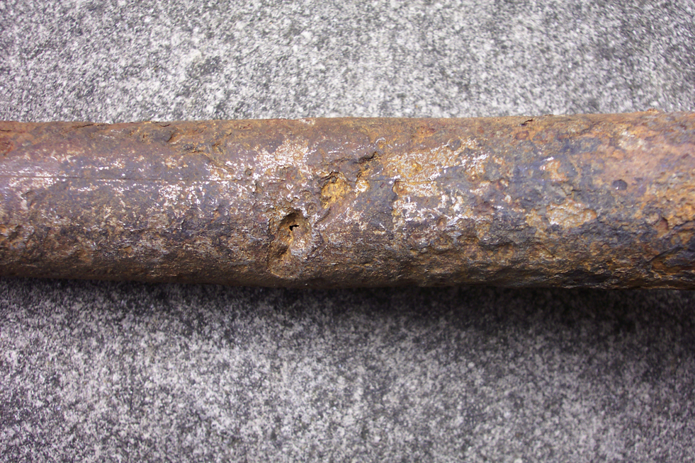
section epub:type=”chapter”> In has been seen that most materials that are unstable in oxygen tend to oxidize. Principally, the main concern is with the loss of material at high temperatures, in dry environments, and it is found that, under these conditions, oxidation is usually controlled by the diffusion of ions or the conduction of electrons through oxide films that are formed on the material surface. Because of the thermally activated nature of the diffusion and reaction processes, it is seen that the rate of oxidation is much greater at high temperature than at low temperature—although even at room temperature, very thin films of oxide do form on all unstable metals. This minute amount of oxidation is important because it helps keep sliding surfaces apart and so influences the coefficient of friction. But the loss of material by oxidation at room temperature under these dry conditions is very slight. This chapter focuses on a different environment for corrosion. Under wet conditions, the situation is different. When mild steel is exposed to oxygen and water at room temperature, it rusts and the loss of metal quickly becomes appreciable. Unless precautions are taken, the life of many things is limited by wet corrosion. In the last two chapters we showed that most materials that are unstable in oxygen tend to oxidize. We were principally concerned with loss of material at high temperatures, in dry environments, and found that, under these conditions, oxidation was usually controlled by the diffusion of ions or the conduction of electrons through oxide films that formed on the material surface. Because of the thermally activated nature of the diffusion and reaction processes we saw that the rate of oxidation was much greater at high temperature than at low, although even at room temperature, very thin films of oxide do form on all unstable metals. This minute amount of oxidation is important: it protects, preventing further attack; it causes tarnishing; it makes joining difficult; and (as we shall see in Chapters 29 and 30) it helps keep sliding surfaces apart, and so influences the coefficient of friction. But the loss of material by oxidation at room temperature under these dry conditions is very slight. Under wet conditions, the situation is different. When mild steel is exposed to oxygen and water at room temperature, it rusts and the loss of metal quickly becomes appreciable. Unless precautions are taken, the life of many things, from cars to bridges, from ships to aircraft, is limited by wet corrosion. The annual bill worldwide for either replacing corroded components, or preventing corrosion (e.g., by painting Scotland’s Forth Bridge), is around US$2.2 trillion—more than 3% of Britain’s GDP. Figure 27.1 shows a graphic example. Why the dramatic effect of water on the rate of loss of material? As an example we shall look at iron, immersed in aerated water (Figure 27.2). Iron atoms pass into solution in the water as Fe++, leaving behind two electrons each (the anodic reaction). These are conducted through the metal to a place where the “oxygen reduction” reaction can take place to consume the electrons (the cathodic reaction). This reaction generates OH− ions which then combine with the Fe++ ions to form a hydrated iron oxide Fe(OH)2 (really FeO·H2O); but instead of forming on the surface where it might give some protection, it often forms as a precipitate in the water itself. The reaction can be summarized by the following, just as in the case of dry oxidation: The formation and solution of Fe++ is analogous to the formation and diffusion of M++ in an oxide film under dry oxidation; and the formation of OH− is closely similar to the reduction of oxygen on the surface of an oxide film. However, the much faster attack found in wet corrosion is due to the following: The result is that the oxidation of iron in aerated water (rusting) goes on at a rate that is millions of times faster than that in dry air. In dry oxidation we quantified the tendency for a material to oxidize in terms of the energy needed, in kJ mol−1 of O2, to manufacture the oxide from the material and oxygen. Because wet oxidation involves electron flow in conductors, which is easier to measure, the tendency of a metal to oxidize in solution is described by using a voltage scale rather than an energy one. Suppose we could separate the cathodic and the anodic regions of a piece of iron, as shown in Figure 27.3. Then at the cathode, oxygen is reduced to OH−, absorbing electrons, and the metal therefore becomes positively charged. The reaction continues until the potential rises to +0.8 V. Then the coulombic attraction between the positive charged metal and the negative charged OH− ion becomes so large that the OH− is pulled back to the surface, and reconverted to H2O and O2; in other words, the reaction stops. At the anode, Fe++ forms, leaving electrons behind in the metal which acquires a negative charge. When its potential falls to –0.6 V, that reaction, too, stops (for the same reason as before). If the anode and cathode are now connected, electrons flow from the one to the other, the potentials converge, and both reactions start up again. The difference in voltage of 1.4 V is the driving potential for the oxidation reaction. The bigger it is, the bigger the tendency to corrode. Figure 27.4 shows a typical Pourbaix diagram (or electrochemical equilibrium diagram)—in this case for copper. The diagrams are maps that show the conditions under which a metal: The axes of the diagram are the electrochemical potential of the metal (in volts) and the pH, which indicates how acidic or alkaline the water is. The three conditions are then represented on the diagram by fields of immunity, corrosion, and passivation. The diagram also shows the line for the oxygen reduction reaction. Note that this slopes, from a potential of +1.23 V when the water is very acid (pH = 0) to +0.4 V when the water is very alkaline (pH = 14). This is because the oxygen reduction reaction produces OH− ions, so increasing the concentration of these ions in the solution (which is what we do when we go from acid to alkaline conditions) shifts the equilibrium position of the reaction. In addition, Figure 27.4 shows that when copper is immersed in water with a pH less than about 6 to 7, it may corrode if the potential of the copper is greater than about 0.2 to 0.3 V. So if there is air in the water, the copper may corrode, because the oxygen reduction line is positioned at a much higher potential. For example, if the pH is 5, the voltage driving force for corrosion is 0.8 V, and because there is no stable oxide film, corrosion may occur. If the pH of the water is between 7 and 12 (from neutral to strongly alkaline), the copper will grow a stable film of copper oxide, which may protect the metal against further corrosion—even though there will still be a driving force of about 0.8 V between the potentials of the copper and the oxygen reduction reaction. It should be emphasized that these diagrams cannot give any indication of the actual rates of corrosion in any situation—they just show where corrosion cannot occur, and where a surface film should form which might prevent or slow down corrosion. Experimental data and field experience in the real environment are essential for corrosion design—even more so because corrosion processes in general, and the barrier properties of surface films in particular, can be very strongly affected by the presence of other ions. These speed up corrosion processes and can attack surface films, which is why seawater—high in chloride ion, Cl−—is such bad news for many metals (see the heavily corroded seawater ballast tank in Figure 27.1). Provided the water is neutral or alkaline (and low in other ions) the rate of corrosion is usually extremely low. This would be expected from the Pourbaix diagram if the oxide film acted as an effective barrier. This is why copper is much used for water pipes. However, if the water is mildly acidic, corrosion “pinholes” can form in the pipe wall (the Pourbaix diagram shows that there is no oxide film below a pH of about 6). Copper is much used for architectural purposes, particularly in the United States and Australia. Figure 27.5 shows a copper rain water pipe on the outside of a building. The thin sheet copper has not corroded significantly, but a protective film has formed on exposure to the elements, which is why the color is darker than freshly polished copper. Older architectural copper usually develops a green color, because the carbon dioxide in the air forms a copper carbonate film. This is just as well, because carbon dioxide also makes the rain water acidic! Copper alloys like brass and bronze are also resistant to corrosion—the fire hydrant shown in Figure 27.6 is as shiny as the day it was made. The Pourbaix diagram for iron is shown in Figure 27.7. In order to have a stable surface film, the pH of the water needs to be above 9, so in most applications (neutral or slightly acidic water) steel will rust unless it is protected. One way of making steel resistant to corrosion is to alloy it with foreign elements which will provide a stable protective film on the surface. Stainless steel is the best known example—adding 18% chromium produces an invisible film of Cr2O3 on the surface, which prevents corrosion in most situations (we saw in Chapter 26 that stainless steel is also very resistant to dry oxidation). Another way is to keep any moisture and/or oxygen away from the surface of the steel (e.g., using paint or epoxy coatings). The Goodwill Bridge (over the river in Brisbane, Australia) has an ingenious way of doing this (Figures 27.8 and 27.9). The main span is supported by two steel arches made from steel plates welded into a box section. The problem with this is that the box sections are too small to be accessed for painting the insides after fabrication is completed—and if they were painted before fabrication the heat of the welding would burn off some of the paint anyway. The solution adopted is to make the box sections pressure tight, and then fill them with dry nitrogen gas under a positive gauge pressure—the result is no moisture and no oxygen either, so the insides cannot corrode! The Pourbaix diagram for aluminum is shown in Figure 27.10. Between pH 4 and 8.5, a thin and very stable film of hydrated aluminum oxide forms, protecting the metal. The corrosion rate of aluminum in pure water is extremely low, even though the driving force for corrosion is very large—about 2.8 volts! However, over time there is a tendency for attack to occur at weak points in the oxide film, so for most outdoor uses—such as window frames, roofs, and cladding—aluminum is first anodized—given a surface treatment that artificially thickens the oxide film to make it even more protective. In the anodizing process, the metal is put into a bath of water containing various additives to promote compact film growth (e.g., boric acid). It is then made positive electrically, which attracts the oxygen atoms in the polar molecules (see Chapter 4). The attached oxygen atoms react with the metal to give more oxide film as shown in Figure 27.11. The film can even be colored for decorative purposes, by adding coloring agents to the bath toward the end of the process. However, in water with lots of other ions, even this anodized film may break down. This is why aluminum corrodes in seawater—the chloride ions are very aggressive to the oxide film. Many books list standard electrode potentials for metals (see Table 27.1). These show the voltage when the metal is in equilibrium with a solution of its ions having a concentration of 1 mol per liter. These are essentially the same voltages as those shown in the Pourbaix diagrams for the horizontal lines at the top of the immunity field when there is no oxide film. The driving force for corrosion can be estimated by subtracting the potential for the metal from that for the oxygen reduction reaction. The potentials for gold, platinum, and palladium are greater than the potential for the oxygen reduction reaction, so these metals cannot corrode—there is no voltage driving force. The other metals have potentials that are less than the potential for the oxygen reduction reaction, so in theory they can corrode. Whether they will in practice depends to a large extent on the barrier properties of any surface films. Because of this, electrode potentials are a poor indicator of actual corrosion rates. Corrosion often attacks metals selectively, and this can lead to component failure much more rapidly and insidiously than one would infer from average corrosion rates. Three important kinds of selective attack are pitting corrosion, intergranular attack, and stress corrosion cracking (see Figure 27.12). In pitting corrosion, preferential attack starts at breaks or weaknesses in the oxide film (sometimes where there are precipitates of compounds in alloys). Once pitting has started, it is virtually impossible to stop it. Figure 27.13 shows a good example: an underground water pipe has corroded from the outside, and although the uniform rate of corrosion is relatively small, there are many areas of pitting corrosion—in the worst, the bottom of the corrosion pit has actually gone through the wall of the pipe. Intergranular attack can occur when the grain boundaries have a lower corrosion resistance than the grains themselves. In extreme cases, the material can literally fall apart at the grain boundaries. In stress corrosion cracking (SCC), a critical combination of stress, material, and corrosive environment can lead to cracks forming and growing under static stress—at stress intensities much less than Kc. Examples are brass in ammonia, mild steel in caustic soda, and austenitic stainless steels in hot chloride solutions. We have already seen one example of a major disaster caused by SCC in Section 16.2.
Wet Corrosion of Materials
Publisher Summary
27.1 Introduction
27.2 Wet Corrosion
27.3 Voltage Differences as the Driving Force for Wet Oxidation
27.4 Pourbaix (Electrochemical Equilibrium) Diagrams
27.5 Some Examples
Copper
Steel
Aluminum
27.6 Standard Electrode Potentials
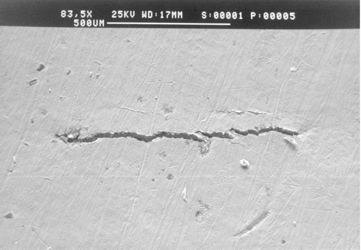
27.7 Localized Attack
Examples
Nominal Stress σ (MN m−2)
Crack Depth a (mm)
Crack Growth Rate da/dt (mm year−1)
4
0.25
0.3
4
0.50
0.6
8
0.25
1.2
Show that these data are consistent with a relationship of form
where  is the stress intensity factor. Find the values of the integer n and the constant A. Assume Y = 1.
Answers
Rates of Uniform Metal Loss