CHAPTER 12
Experimental Investigation and Optimization of Process Parameters in Oblique Machining Process for Hard-to-Cut Materials Using Coated Inserts
1Mechanical Engineering Department, G. H. Patel College of Engineering & Technology, Vallabh Vidyanagar, Gujarat, India
2Mechanical Engineering Department, CHARUSAT, Changa, Gujarat, India
ABSTRACT
The high-speed machining process is being widely used in the automobile and aeronautical industries these days where superfine surface finish is the basic requirement. For such a process, a force modeling is done that considers the friction law which is the function of the tool-chip interface temperature which is, in turn, used to calculate different parameters, and ultimately the forces evolved in the machining process. The influence of parameters like velocity and depth of cut on cutting forces is investigated for the empirical relation of the coefficient of friction derived for CRS 1018 for different hard-to-cut materials. For this purpose, tests are carried out turning center for these materials using cryogenically treated cemented carbide tool inserts. The effect of cutting force variation is analyzed experimentally and is compared with the analytical results. Also, optimum cutting force, surface roughness, and power consumption are found out using Taguchi’s orthogonal array. For the machining of the Hard-to-cut materials, the temperature aspect plays an important role in the forces evolved during the process. This includes the temperature evolved in the primary shear zone as well as the tool-chip interface.
12.1 INTRODUCTION
Machining of the hard-to-cut materials is a very critical aspect in the area of manufacturing technology. It is for this reason, the prediction of forces becomes the area of concern as the type surface finish obtained is majorly driven by the forces evolved. The prediction of forces may lead us to the prediction of tool wear thereby tool life and the surface finish. When we deal with high-speed machining, the temperature evolved during the process also plays an important in the calculation of the forces. High-speed steel (HSS) is widely used in manufacturing tool materials which are in turn used to machine the workpiece components. So for that purpose, cutting speed of over 120 m/min is considered in our analysis. So, the present study mainly focuses on the effect of different parameters for the oblique cutting process. The analysis of the orthogonal cutting process can be extended to the oblique cutting process using the transformation matrix in Tounsi et al. [1].
To incorporate the thermal effect in the oblique cutting process, some of the parameters like strain rate sensitivity and strain hardening have been considered in Oxley et al. [2]. The primary shear zone has been assumed to have been divided into two unequal parts Astakhov et al. [3]. A coulomb friction law as considered in Moufki et al. [4], has been used which gives the dependence of the coefficient of friction on the tool-chip interface temperature. Based on the empirical relations Moufki et al. [5], a more simplified relation for the coefficient of friction has been considered. For the analysis, the process has been considered as stationary and the analysis is for the one-dimensional flow. In addition to that, the shearing in the band is assumed to be Molinari and Clifton [6]. The chip flow angle ηc is calculated as the function of the cutting velocity V, the rake angle αn, friction angle λ, and the inclination angle λs.
This law considers a constant thickness of the primary shear zone h = 0.025 mm. The undeformed chip thickness is small compared to the width of cut and the chip is considered to have formed under approximately plain strain conditions. The chip flow direction is normal to the cutting edge. The chip flow direction is an important factor as it plays an important role in the tool chip contact length. The pressure along the tool chip interface is also considered in the analysis. The anisotropy of the material is not considered in the present analysis as in Johnson and Mellor [7]. The effect of the parameters like the Taylor-Quinney is assumed to be a constant value as the effect of the sliding and sticking zone has been neglected in the present analysis Kushner [8].
The present analysis is done using the MATLAB interface for the mathematical modeling Bhatt et al. [9]. For the mathematical modeling, in order to solve the equations for the stress induction in the primary shear zone, the results seemed to be diverging and the solutions of the equations were obtained in the form of hypergeometric functions. So to simplify the problem, there was an assumption made that the stresses induced at the entrance of the primary shear zone was equal to the yield strength of the material Bhatt, et al. [10]. Taking this value as the reference, the iterations were carried out and the stress variation along the primary shear zone has been obtained.
For the effect of Depth of Cut Cutting and Thrust Force, Dudzinski et al. [18] stated that with an increase in the depth of cut the cutting forces increase for a particular constant value of the velocity. Here the value of velocity is taken as 120 m/min. This trend in analytical modeling has been validated by the experimental results. The numerical values of the experimental results are a bit different from the analytical model as the operating conditions like the feed rate, the diameter of the workpiece, length of the cut, etc. are not specified in Moufki et al. [4] so may differ from the experimental parameters considered. The increase in forces with an increase in the depth of cut can be understood as the force required to deform a larger thickness of the material is large [19]. This is because the number of bonds needed to be broken to initiate plastic deformation are more in the higher depth of cut compared to that in a smaller depth of cut. The range of the thrust force is very negligible as compared to the cutting force. This trend can also be observed in the analytical and experimental results. The study of HSS has been done in this chapter and the comparison for both the materials in terms of experimental results as well as analytical results has been shown.
12.2 ANALYTICAL MODELING OF OBLIQUE CUTTING PROCESSES
The effect of cutting velocity and depth of cut on cutting force, Thrust force, and interface temperature have been studied for Hard-to-cut materials. In the present study, we have considered HSS as our workpiece material. Various coated tool inserts have also been considered in the study and the effect of various cutting parameters on the tool wear have been demonstrated through microscopic images of the cutting edge under consideration.
12.2.1 FOR DRY MACHINING
• Constant Speed, Constant Feed, and Variable Depth of Cut (Figures 12.1–12.3).
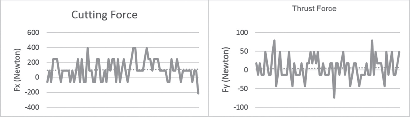
FIGURE 12.1 Cutting force and thrust force plot for conditions: V = 2.638 m/s; DOC = 0.15 mm; feed = 0.06 mm/Rev.
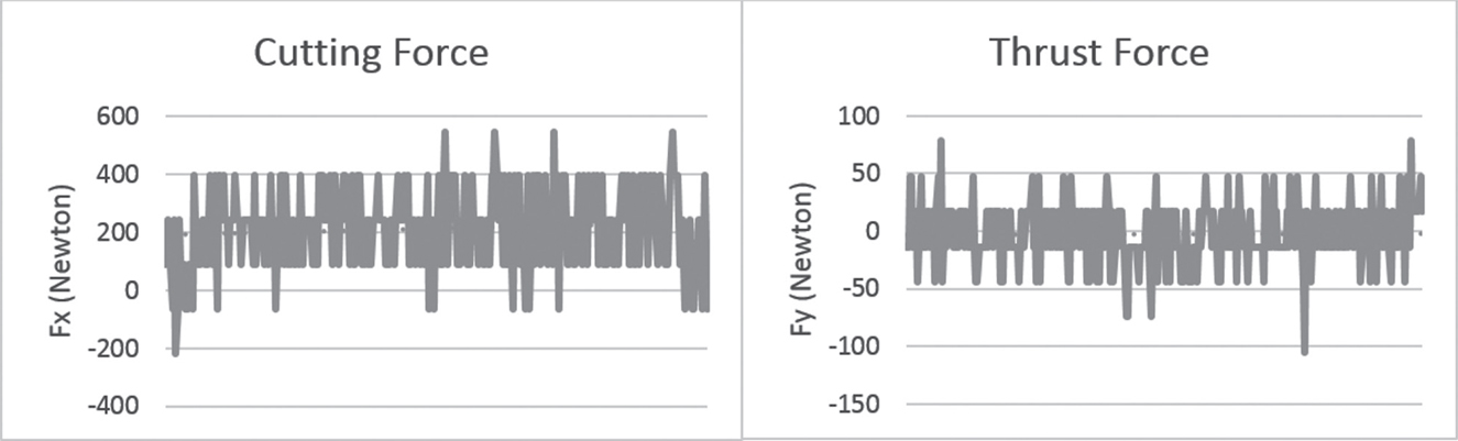
FIGURE 12.2 Cutting force and thrust force plot for conditions: V = 2.638 m/s; DOC = 0.2 mm; feed = 0.06 mm/Rev.
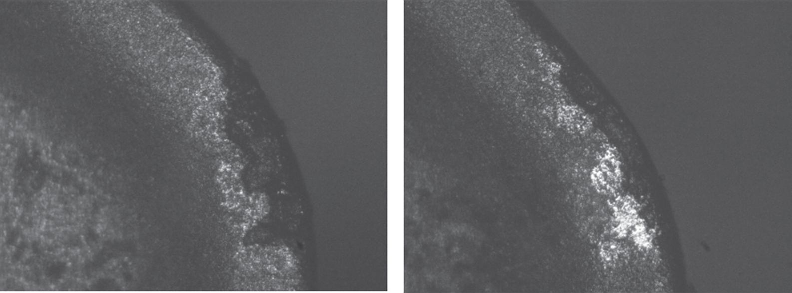
FIGURE 12.3 Cutting force and thrust force plot for conditions: V = 2.638 m/s; DOC = 0.15 mm; feed = 0.06 mm/Rev and V = 2.638 m/s; DOC = 0.2 mm; feed = 0.06 mm/Rev.
Machining parameters play a very important role in the kind of finished component that is manufactured. In the same regards, we have considered a case wherein the cutting speed and the feed are kept constant for the process, and the depth of cut is varied. In such a case, the cutting force obviously increases as shown in the graphs obtained during the machining process. But the variation effect on the thrust force is negligible with an increase in the depth of cut. This means that the surface finish should not have such an effect by variation in the depth of cut during the machining process. This is verified by the surface roughness experimental data shown in Table 12.3.
• Constant Depth of Cut, Constant Feed, and Variable Speed (Figures 12.4–12.6).
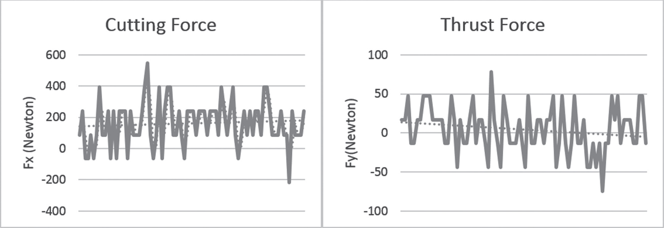
FIGURE 12.4 Cutting force and thrust force plot for conditions: V = 3.72 m/s; DOC = 0.2 mm; feed = 0.02 mm/Rev.
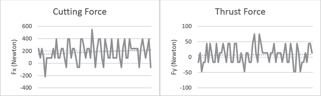
FIGURE 12.5 Cutting force and thrust force plot for conditions: V = 2.638 m/s; DOC = 0.2 mm; feed = 0.02 mm/Rev.
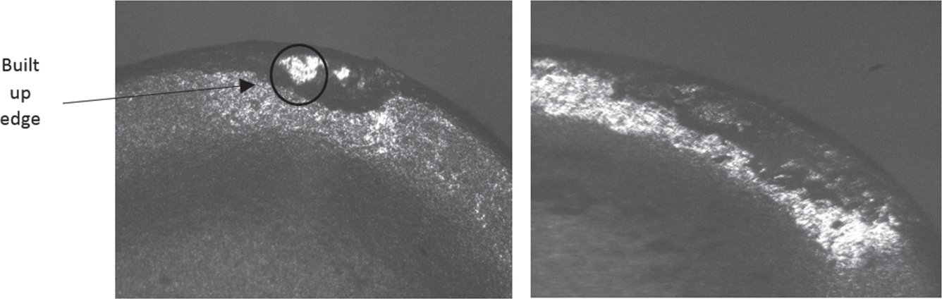
FIGURE 12.6 Cutting force and thrust force plot for conditions: V = 3.72 m/s; DOC = 0.2 mm; feed = 0.02 mm/Rev and V = 2.638 m/s; DOC = 0.2 mm; Feed = 0.02 mm/Rev.
The next case that we have considered is a case wherein the cutting feed and the depth of cut are kept constant for the process and speed is varied. In such a case, the cutting force almost negligibly varying as shown in the graphs obtained during the machining process. The variation effect on the thrust force is negligible as well. But as the length of the cut is increasing, the slight droop can be found in these quantities which maybe because of the thermal softening effect. For a case with higher velocity, a built-up edge formation can be found which suggests that the temperature reached during the machining process was sufficient enough to weld the debris onto the burnt-out part in on the tooltip as shown.
• Constant Speed, Constant Depth of Cut, and Variable Feed (Figures 12.7–12.9).
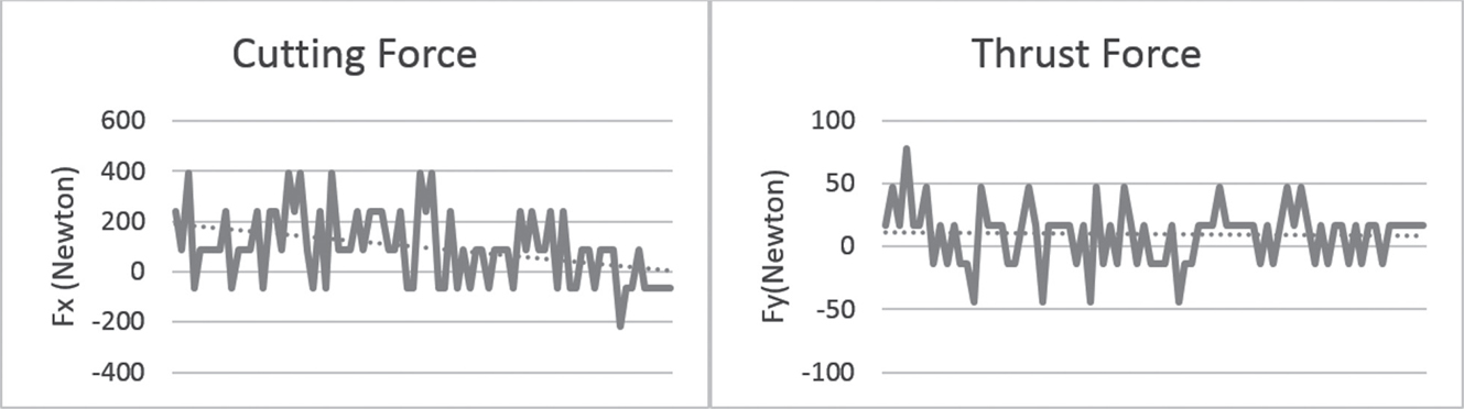
FIGURE 12.7 Cutting force and thrust force plot for conditions: V = 5.2 m/s; DOC = 0.1 mm; feed = 0.04 mm/Rev.
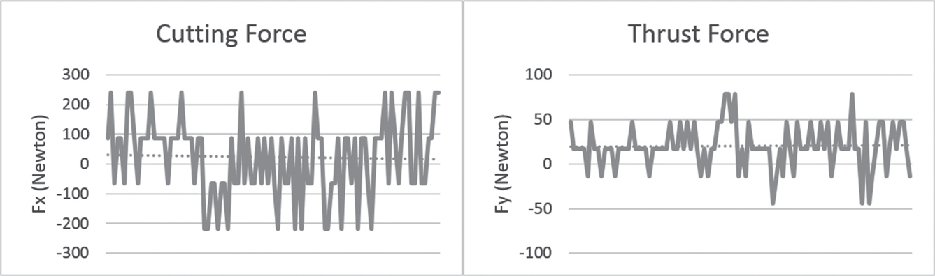
FIGURE 12.8 Cutting force and thrust force plot for conditions: V = 5.2 m/s; DOC = 0.1 mm; feed = 0.02 mm/Rev.
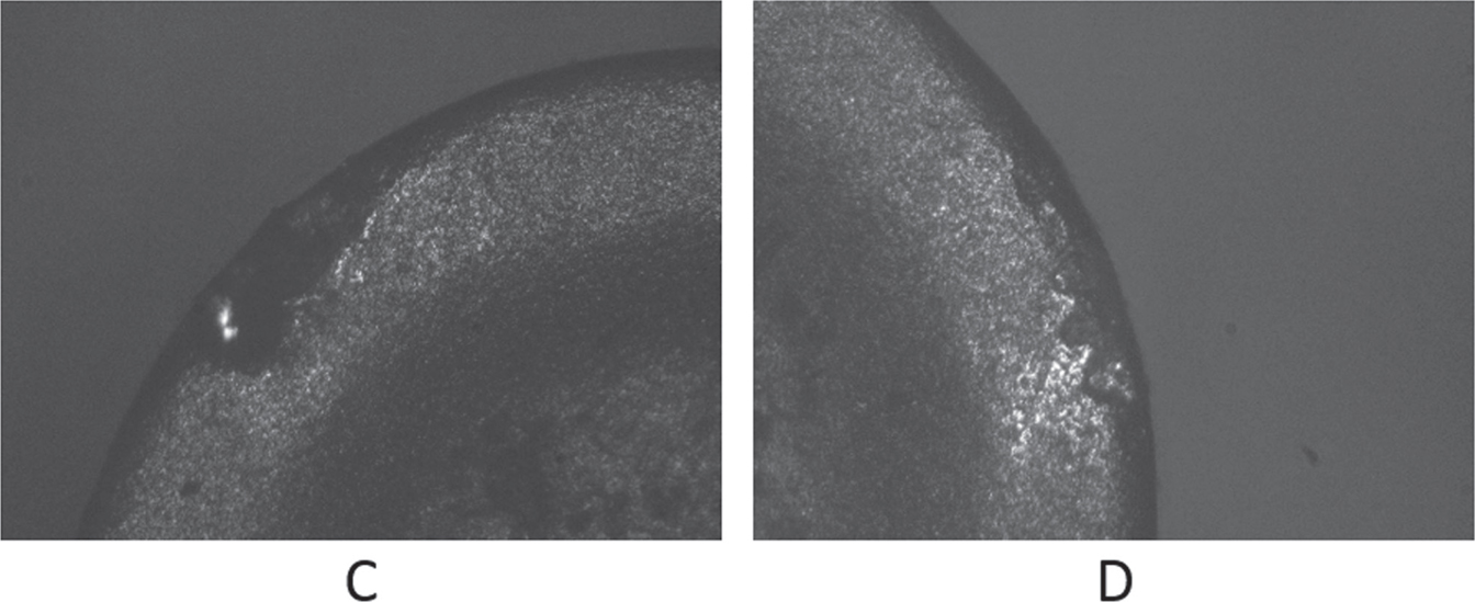
FIGURE 12.9 Cutting force and thrust force plot for conditions: V = 5.2 m/s; DOC = 0.1 mm; feed = 0.04 mm/Rev and V = 5.2 m/s; DOC = 0.1 mm; Feed = 0.02 mm/Rev.
Here cutting speed and the depth of cut are kept constant for the process and feed is varied. In such a case, the cutting force is significantly high for a higher feed rate as shown in the graphs obtained during the machining process. The variation effect on the thrust force is negligible again just like in case of varying depth of cut. But the slight droop can be found in these quantities which maybe because of the thermal softening effect, as the length of cut is increasing. The tool wear in case of higher feed rate is more than that in case of a lower value of feed rate. But again, the wear is not significant if we compare it with other parameters studied in this literature.
12.3 EFFECT ON TOOL WEAR FOR WET AND DRY MACHINING
The above figures clearly suggest the difference in the effect of the tool wear due to wet machining and dry machining. Figures 12.10(a)–(c) are the tool wear profiles observed under the metallurgical microscope for 50x zoom under dry machining conditions. It can be observed that in the case of dry machining, the built-up edge formed can be identified on the burnt-out portion. Built-up edge formation has been shown in one instance under dry machining (Figure 12.10b).
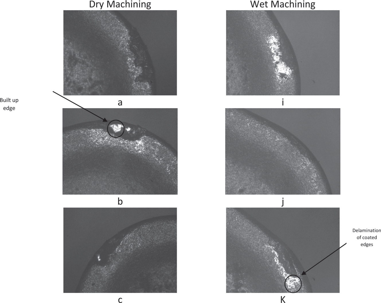
FIGURE 12.10 Tool wear for dry and wet conditions.
We can also observe that there’s no or hardly any delamination on the tool tip in the case of dry machining. Similarly, Figures 12.10(i)–(k) are the tool wear profiles observed under the metallurgical microscope for 50x zoom under wet machining conditions. But in the case of wet machining, we can observe the surface delamination of the coating. Though, the figures suggest that there’s no built-up edge formed on the tool surface in case of wet machining. This can be explained in a way that for built-up edge to form, proper adhesion of the debris and the tool surface must take place. But because of the use of a coolant, we can’t find any built-up edge formed as the coolant takes away the heat generated during the machining process. Thus in absence of heat required to soften the metal and allow it to undergo adhesion, there is no built-up edge formation in wet machining conditions.
12.4 COMPUTATIONAL INVESTIGATION
Figure 12.11 shows the variation in forces (cutting and thrust) and temperature over a primary shear zone. As in line with our experimental results, the force values increase with the cutting velocity. But an important observation that one can go for from the force plots is that at a lower value of cutting velocity, the length of the tool chip interface is lower. Also, the temperature at the interface is higher for higher velocity plots as observed in the figure. As the velocity increases, the point of maximum temperature shifts farther from the tool tip. This aspect is yet to be analyzed in the experimental results which can be considered as the future work for this course which may help us the probable location of the built-up edge formation.
FIGURE 12.11 (A, B) Cutting force, thrust force, and temperature variations for two different conditions of cutting speed.
FIGURE 12.11 (C, D, E, F) Cutting force, thrust force, and temperature variations for two different conditions of cutting speed.
12.5 EXPERIMENTAL INVESTIGATION
The design of experiment study is carried out to plan and construct the machining of hard-to-cut material. For this study, Taguchi’s L-18 orthogonal array is selected with five variables and mixed-level design. Taguchi’s orthogonal array gives near the same result as full factorial design, Solanki and Desai [11]. Minitab statistical software is used to construct and analyses the experiment. Parameters selected for this experiment are cutting conditions, cutting tool, speed (rpm), feed rate (mm/rev.), and depth of cut (mm). For high speed, machining it is important to do the machining above the cutting velocity of 120 m/minute. The diameter of the workpiece is 71 mm and corresponding to that minimum chuck speed is 538 rpm. The outlet of design from the Minitab is as shown in Table 12.1. Cutting conditions are selected as wet and dry; cutting tools used for this experiment are-CNMG235, CNMG 4235 and 710; feed rate based on initial study selected as 0.02, 0.04 and 0.06 m/revolution; depth of cut is selected as 0.10, 0.15, and 0.20 mm; cutting speed is selected as 710, 1000, and 1400 rpm.
TABLE 12.1 Outlet of Design of Experiment (L-18 OA)
With process parameters mentioned in Table 12.1, the response variable selected for optimization study are surface roughness and material removal rate.
12.6 OPTIMIZATION OF SURFACE ROUGHNESS AND MATERIAL REMOVAL RATE
With the input process parameters mentioned in Table 12.1, experiments are carried out in random order. The machining process is carried out on a conventional lathe machine. Surface roughness is measured with the help of sophisticated surface texture measuring instrument SV-2100 from Mitutoyo Corporation. Measurement conditions are selected as sample length of 25 mm, the total number of 8 samples, and pitch of 1.0 µm with filter setting of Gaussian element and speed of stylus movement is 0.5 mm/second. The outcome profile of the surface roughness for all the iteration is shown in Table 12.2. To measure the material removal rate during the turning process, a cut for a specific length of 25 mm is carried out. Weight of specimens before and after the turning process is measured. The outcome of the experiment results is mentioned in Table 12.3.
TABLE 12.2 Surface Texture Profile for L-18 OA
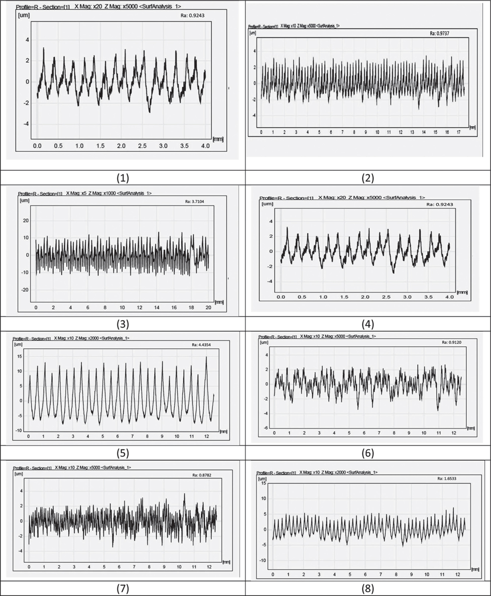
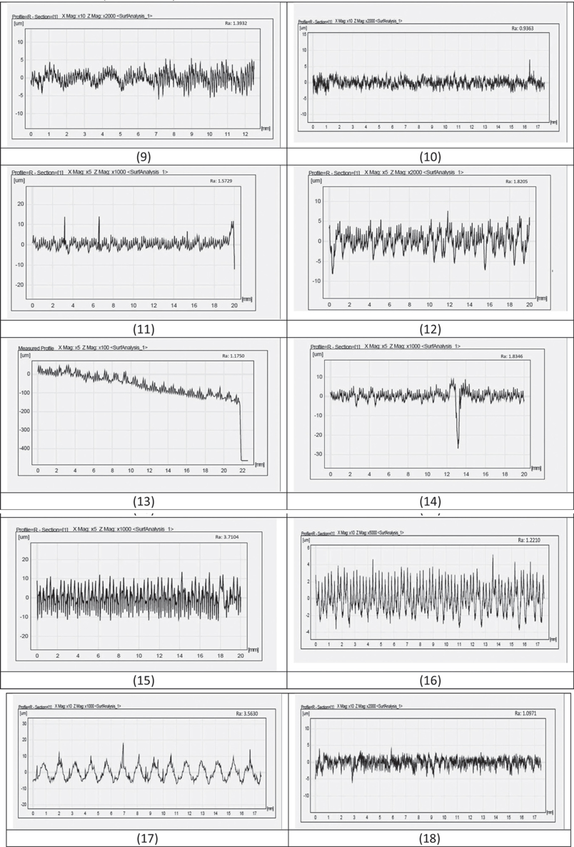
TABLE 12.3 Outcome Results of MRR and Ra for L-18 OA
The significance of the parameters is studied on the basis of experimental data. As the output characteristic (surface roughness) is to be studied for this process, Taguchi’s signal to noise(S/N) ratio concept is utilized. Because surface roughness is a small-the-best type of characteristic, the S/N ratio formula used for this analysis is 10log(Y/S), where y is considered as average and s is the standard deviation [16]. The values of S/N ratio are calculated for all 18 experiments and these values of S/N ratio further analyzed for checking the statistical significance of parameters. The graph of S/N ratio for surface roughness is shown in Figure 12.12. From the graph of S/N ratio, optimum values for process parameters should be selected at a higher level. Working condition at level-1 (wet), tool at level-1 (CNMG-7115), feed at level-1 (0.20 mm/ rev), the speed at level-3 (1400 rpm), and depth of cut at level-1 (0.10 mm), should be selected to minimize the roughness of the surface, Wu and Hamada [12].
FIGURE 12.12 S/N ratio plot for surface roughness (Ra).
As the material removal rate is a larger-the-best type of characteristic, the S/N ratio formula used is 10log (1/Y)/S). The values of S/N ratio are calculated for all experiments. The plot of S/N ratio for MRR is shown in Figure 12.13. From the graph of S/N ratio, optimum values for process parameters should be selected at a higher level. Working condition at level-2 (dry), cutting tooltip at level-2 (CNMG-711), cutting speed at level-1 (710 rpm), Feed rate at level-1 (0.02 mm/rev), and depth of cut at level-3 (0.20) should be selected to maximize MRR.
To investigate the process parameters, ANOVA (analysis of variance) are performed, Montgomery and Runger [13], as shown in Table 12.4. It is not convenient to identify the significance level of process parameters based on S/N ratio graph. Thus, to establish statistical significance, the confidence interval is assessed with 95% (α = 0.05) for the differences in mean. Using Minitab software depth of cut had DF (degree of freedom) (2), the adjacent sum of square (Adj SS) (26.985), adjacent mean square (Adj MS) (26.9853), F-value (4.63) and P-value (0.042). Since p ≤ 0.05, depth of cut is a significant factor for surface roughness, Gijo and Scaria [14]. For working conditions, cutting tooltip, speed, and feed rate have p≥0.05, they are not statistically significant.
FIGURE 12.13 S/N ratio plot for MRR.
TABLE 12.4 Analysis of Variance for Surface Roughness
To assess the significance of the process parameter on MRR, ANOVA is conducted as shown in Table 12.5. The ANOVA study is conducted with 95% of the confidence interval. As the p-value for the parameters has greater than 0.05, the null hypothesis gets accepted. Hence, none of the factors is significant in this study for MRR.
TABLE 12.5 Analysis of Variance for MRR
KEYWORDS
• analysis of variance
• degree of freedom
• dry machining
• high-speed steel
• machining parameters
• thrust force
REFERENCES
1. Tounsi, N., Vincenti, J., Otho, A., & Elbestawi, M. A., (2002). From the basics of orthogonal metal cutting towards the identification of the constitutive equation. Int. J. Mach. Tools Manuf., 42(2), 1373–1383.
2. Oxley, P. L. B., & Welsh, M. J. M., (1963). Calculating the shear angle in orthogonal metal cutting from fundamental Stress, strain, and strain rate properties of the work material. In: Proceedings of the 4th International Machine Tool Design and Research Conference (pp. 73–86). Oxford.
3. Astakhov, V. P., Osman, M. O. M., & Hayajneh, M. T., (2001). Re-evaluation of the basic mechanics of orthogonal metal cutting: Velocity diagram, virtual work equation, and upper bound theorem. Int. J. Mach. Tools Manuf., 41, 393–418.
4. Moufki, Molinari, A., & Dudzinski, D., (1998). Modeling of orthogonal cutting with a temperature-dependent friction law. J. Mech. Phys. Solids, 46(10) 2103–2138.
5. Moufki, A., Dudzinski, D., Molinari, A., & Rausch, M., (1999). Thermo viscoplastic modeling of oblique cutting: Forces and chip flow predictions. International Journal of Mechanical Sciences, 42(2000), 1205–1232.
6. Molinari, A., & Clifton, R. J., (1987). Analytical determination of shear localization in thermoviscoplastic materials. Journal of Applied Mechanics, 54, 80612.
7. Johnson, W., & Mellor, P. B., (1983). Engineering Plasticity. John Wiley & Sons, New York.
8. Kushner, V. S., (1982). Thermo Mechanical Approach in Metal Cutting. Irkutsk Univ. Pabl. Ltd, Irkutsk, Russia.
9. Bhatt, P., Tewari, A., & Raval, H. K., (2018). Modeling of oblique cutting process using coulombs friction law for Ti-6Al-4V Alloy. Materials Today: Proceedings, 5(11), 23596–23602.
10. Bhatt, P., Tewari, A., & Raval, H. K., (2018). Parametric study and modeling of orthogonal cutting process for AISI 4340 and Ti-6Al-4V alloy. Materials Today: Proceedings, 5(2), 4730–4735.
11. Solanki, M., & Desai, D., (2015). Comparative study of TQM and six sigma. International Journal of Industrial Engineering and Technology, Trans Stellar Publication, 5(4), 1–6.
12. Wu, C. F. J., & Hamada, M., (2011). Experiments-Planning, Analysis, and Parameter Design Optimization. John Wiley, New York, NY.
13. Montgomery, D. C., & Runger, G. C., (2007). Applied Statistics and Probability for Engineers (4th edn.). John Wiley & Sons, Inc, London.
14. Gijo, E. V., & Scaria, J., (2010). Reducing rejection and rework by application of six sigma methodology in the manufacturing process. International Journal of Six Sigma and Competitive Advantage, 6(1/2), 77–90.
15. Binglin, L., Yujin, H., Xuelin, W., Chenggang, L., & Xingxing, L., (2011). An analytical model of oblique cutting with application to end milling. Machining Science and Technology: An International Journal, 15(4), 453–484. doi: 10.1080/10910344.2011.620920.
16. Taguchi, G., (1987). Systems of Experimental Design (Vols. 1 and 2). UNIPUB and American Supplier Institute, New York, NY.
17. Astakhov, V. P., & Osman, M. O. M., (1996). An analytical evaluation of the cutting forces in self-piloting drilling using the model of the shear zone with parallel boundaries. Part 1: Theory. International Journal of Machine Tools and Manufacture, 36(11), 1187–1200.
18. Dudzinski, D., & Molinari, A. (1997). A modelling of cutting for viscoplastic materials. Int. J. Mech. Sci., 39(4), 369–389.
19. Merchant, M. E. (1944). Basic mechanics of the metal cutting process. ASME J. Appl. Mech. 66, 168–175.