Department of Mechanical Engineering, IIT Jodhpur, Karwar, Jodhpur, Rajasthan, India, E-mail: ravib@iitj.ac.in (B. Ravindra)
ABSTRACT
Sensors are an integral part of mechatronic systems. It is common to introduce sensor characteristics such as range, span, error, accuracy, sensitivity, hysteresis, non-linearity, stability, dead band, resolution, etc., in a basic course on mechatronics. The static and dynamic responses of sensors are also explained in this context. Introducing real-life case studies, while teaching sensors, can motivate students. Recent advances in sensors include wireless transmission and energy harvesting from ambient sources. An interesting case study to understand these developments is the tire pressure monitoring sensor (TPMS). Underinflated tires can lead to accidents. Reduction in tire pressure may also increase wear out of tires and reduction in fuel economy. Tire pressure monitoring is a solution to address these issues. TPMS is made mandatory in some countries. In the existing implementation of TPMS in automobiles, the energy source is a CR battery. Battery operated TPMS have certain limitations. Frequent replacement of the battery is a concern for the user. The idea of using vibrational energy of the tire to power TPMS has been proposed in the literature as an alternative to batteries.
5.1 INTRODUCTION
Sense and respond features are ubiquitous in mechatronic systems. The selection of physical quantity to be sensed is very important in their design. The availability of commercially off the shelf (COTS) sensors made this task simple in recent years. Sensors are often classified based on the input stimuli such as temperature sensor, pressure sensor, humidity sensor, etc. Another classification is based on an analog or digital sensor. The nature of the transduction of the input stimuli to a convenient electrical signal is a critical step. The noisy signal from the sensor is passed on to the signal conditioning circuit. The output of this circuit is fed to the data acquisition (DAQ) system. The following classification of sensors is often used in literature:
1. The physical principle on which the sensor works such as Hall Effect, piezoelectric effect, Seebeck effect, etc.
2. Whether the sensor is a contact/non-contact type.
3. Whether the sensor is wired or wireless.
4. If the sensor requires energy to operate then it is referred to as active else passive.
Sensor selection involves in a clear understanding of the technical specifications given by the manufacturer. The following attributes need to be considered in this regard:
1. Sensitivity of the sensor which is the smallest detectable change in the output of the sensor to a change in the input, evaluated at a specific input.
2. Gain of the sensor defined as the absolute value of the output signal relative to the absolute value of the input signal.
3. Full scale output that specifies the working range of the measured physical quantity.
4. Span of the sensor which is the difference between electrical sensor output values corresponding to the max and min values of the electrical signal.
5. Threshold of the sensor is the minimum value of the input signal needed to stimulate or activate the sensor output.
6. Resolution refers to the incremental change in the input signal that would cause a corresponding change in the sensor output.
7. Response time of the sensor.
8. Linearity of the sensor.
9. Repeatability and Accuracy of the sensor.
10. Precision, Error, and uncertainty of the sensor.
11. Dynamic response of the sensor.
It is typical in mechatronics courses to introduce various kinds of sensors to the students. A typical reference material for this task is the IEEE Handbook of sensors. An alternate pedagogical approach is to present a case study on sensors and emphasize the system integration and design aspects from a mechatronic point of view. It may even be important to expose students to regulatory aspects of engineering systems and how mechatronics and sensors can play a role in meeting the requirements of society. The case of tire pressure monitoring sensors (TPMS) is discussed in this article from this perspective.
5.2 NEED OF TPMS
Most of the drivers are not experienced enough to judge whether tire pressure is correct or not according to specifications. On average, there are ten centimeters thicker air and tire layers between rim and ground. Because of the underinflated tires, there has been a significant number of accidents occurring each year. One of the common causes of accidents is the failure of the tire due to lower pressure. Even if lower pressure may not cause tire failure it can still cause a fatality. In under-inflated tires, the driver does not get good control and may also lead to an increase in stopping distance. The NHTSA (National Highway Traffic Safety Administration) report estimates that the tire pressure sensor system in vehicles would prevent several fatalities.
The contact patch of tire increases due to under-inflated tires, so the effective radius of tire reduces. This way mileage and fuel economy of the vehicle may also get affected. For example, tires that have 6psi lower than the recommended pressure can cause a 5% decrease in fuel economy. That is if any vehicle has a mileage of 20 km per liter then due to under-inflation of 6 psi causes 19 km per liter. In the long term, it is a significant loss to the economy. Not only mileage and fuel economy are affected due to under-inflation of tires but also tires wear very fast closer to sides. The tire expert Rastetter estimated that the tire wears out 25% faster if the pressure is 6 psi below the specification [1]. It is still a challenge to save this loss in terms of tire wear and fuel economy. This loss is primarily due to the lack of monitoring of the tire pressure. TPMS (tire pressure maintenance system) is the best technological option that alerts the possibility of underinflated tires to the driver. Tires typically lose about one psi of pressure each month. This depends on environmental conditions as well. The seasonal changes and driving patterns also may play a role.
It is interesting to take a look at the regulatory aspect of TPMS worldwide. As per a report of freescale, in the United States FMVSS138 mandates TPMS for new vehicles starting from 2005. In the European Union EC661–2009 mandates TPMS for all new vehicles starting from November 2014. In South Korea and Japan TPMS is mandated on passenger cars from 2013 for new models. In Russia, Kazakhstan, Belarus, Indonesia, Israel, Malaysia, Philippines, TPMS may be required for all new vehicles starting November 2014. Similar efforts are underway in China as well. Thus, there is a strong impetus from the regulatory authorities to install TPMS in all new vehicles.
5.3 TYPES OF TPMS
At present, TPMS can be divided mainly into two types: one of them is based on the wheel speed (also referred to as indirect TPMS). This system compares the differences of the speed values between the tires by the ABS wheel speed sensor system of the vehicle to achieve the purpose of monitoring the tire pressure. The main drawback of this system is that it can’t judge the situation when more than two tires are under normal pressure. If the vehicle speed is over 100 km/hr, a large error may result. Thus, only when the vehicle speed is below a certain threshold value, indirect TPMS seems to be useful.
The second option is based on the pressure sensor (also referred to as direct TPMS). This TPMS system makes use of a pressure sensor which is installed in each tire of the vehicle to measure the tire pressure and that data is shown in driver’s display and monitors the pressure of each tire. These days many cars are fitted with tire pressure sensors. Rapid miniaturization of sensors is an important development in the deployment of TPMS. The four sensors are connected in a wireless sensor network and the tire pressure information is displayed wirelessly. The main goal is to reduce the power consumption of the wireless sensors. This chapter deals with only direct TPMS as described in the next section.
5.3.1 DIRECT TPMS
A direct tire pressure monitoring system refers to a pressure sensor directly mounted on the wheels or tires of a vehicle. The pressure information is often transmitted to the vehicle using radio frequency (RF) technology. Typical specification of a Microchip TPMS is given below:
• Operating voltage: 2.3–3.3 V.
• Low voltage alert threshold: 2.3 V.
• Stand by current: ~12 µA.
• UHF transmitting frequency: 433.92 MHz.
• UHF transmission baud rate (TE): 100, 200, 400, 800 µs selectable (system default is 400 µs).
• UHF range: ~10 meters.
• LF frequency: 125 kHz.
• LF input sensitivity: ~3 mVPP.
• LF range: Up to 3 meters.
• Pressure sensor type: Analog.
• Pressure sensor range: 1–7 bars absolute.
• Pressure sensor temperature range: 40–125°C.
A direct TPMS is often equipped with the following components in the vehicle:
1. A direct TPM sensor built-in to the back of the valve stem on each one wheel.
2. A TPM warning light.
3. Unique identifier for the tires providing the direction of rotation and speed.
4. A microcontroller unit.
5. Antenna.
6. Batteries.
In existing TPMS a 3 V NiHM (CR2320) battery is often used. Battery operated TPMS have certain limitations and owner’s dissatisfaction with battery replacement is a concern. Piezoelectric based tire vibration harvesting is an option in this case.
5.4 CHALLENGES IN TPMS
TPMS must be designed to meet the following requirements:
• The pressure sensor must be small enough because it should be fit inside the tire.
• A small power source to supply power to the sensor.
• The amount of data from the sensor (and the range) that should be sent to the driver’s display.
• The environmental influences on sensor data and reliability of sensors.
5.5 Energy Harvesting Through Piezo Bimorphs
The idea of using piezoelectric harvesting of tire vibrations to power TPMS is discussed here. A discussion of other challenges outlined above can be found in the relevant literature. In the existing technology, the battery is used to power the sensor. But batteries have limitations in terms of total discharge period and replacement issue. Can batteries as power sources be replaced with piezoelectric energy harvester to meet the requirement of power for the sensor? This idea is around for over a decade. Several prototypes have been made but to the best of the author’s knowledge, no commercial solution seems to have been deployed in real vehicles. The space constraints and the tuning of the piezo harvester to the tire vibrations seem to pose some hurdles.
Energy harvesting through piezoelectric materials in the form a bimorph that can extract power from ambient vibrations has been thoroughly researched in the literature. These materials exhibit electromechanical coupling between mechanical and electrical domains. Energy harvested is high when the piezo bimorph is excited at the resonance frequency. Various factors affecting the natural frequency of the piezoelectric bimorph are studied in the literature. Various piezoelectric materials, substrates, and geometrical conditions are compared for energy harvesting from vibrations to power TPMS in the literature. The commercial feasibility of this option needs to be compared with existing battery-operated tire pressure monitoring systems.
5.6 PIEZOELECTRIC ENERGY HARVESTER
A schematic diagram of the bimorph structure for the TPS module is shown in Figure 5.1. A piezoelectric energy harvester is a cantilever beam of piezoelectric plates and metallic plates bonded tightly. As shown in Figure 5.1, the bimorph is fixed at one end and free at another end. The free end vibrates transverse to the length direction, to produce power.
The harvester fits in the shell, so that the bender will not get affected from its surroundings and in the shell, the bender can vibrate freely. The following are the basic design elements for the module:
• Selection of piezoelectric material;
• Selection of metallic layer;
• Harvester is fixed at one end. An insulating mount is required to fix the bender from one end;
• Harvester is free from another end, so that it can vibrate freely. Sufficient free space should be in the shell for the vibration of free end freely;
• The harvester is embedded in a shell. So, a shell or package should be designed to protect the bender as shown in Figure 5.2.
This piezoelectric energy harvester comprises of two piezoelectric layers and three metallic layers. The proof mass is provided to tune the natural frequency of harvester. The whole assembly is embedded in a cylindrical shell.
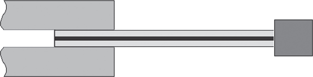
FIGURE 5.1 Piezo bimorph with a tip mass.
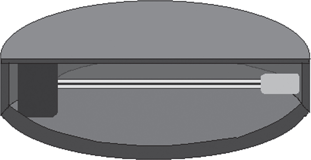
FIGURE 5.2 Energy harvester embedded in the shell.
5.7 DESIGN OF TPMS WITH PZT BIMORPH HARVESTER
The challenges are (i) to know the natural frequency of the tire; actually, it can vary very randomly due to change of load, change of speed, change of roads, etc., (ii) design the bimorph which has natural frequency near to the natural frequency of the tire, (iii) design of electrical circuit which will supply undisrupted power to the sensor and required voltage to the sensor, (iv) compact and solid casing for the whole TPMS.
The natural frequencies can be estimated from the solution of the governing equations of the vibrating cantilever beam with a tip mass. The tip mass selection can be made to bring the natural frequency down to match the tire lateral vibrations. The beam with no tip mass needs a distributed parameter mathematical model. The beam with large tip mass can approximate a lumped mass model. Therefore, It is necessary to overview the governing equations of the distributed parameter base excitation model. The standard Euler-Bernoulli beam assumptions (neglecting shear deformation and rotary inertia) for a uniform cantilever beam are used here. The following partial differential equation describes the free vibrations of the beam (Figure 5.3).
 (5.1)
(5.1)
The mathematical model used here is based on Erturk and Inman [9, 10]. It describes different parameters that affect the natural frequencies of PZT bimorphs. On the basis of these parametric studies, one can choose proper geometrical and mechanical constraints to obtain desired natural frequency. The bimorph with a tip mass and an electrical circuit to evacuate power is shown in Figure 5.4.
Assuming damping to be negligible, ωr the undamped natural frequency of the rth vibration mode in short circuit conditions (i.e., as RL→0) is given by:
 (5.2)
(5.2)
The eigenvalues of the system (λr for rth mode) are determined from following equation:
 (5.3)
(5.3)
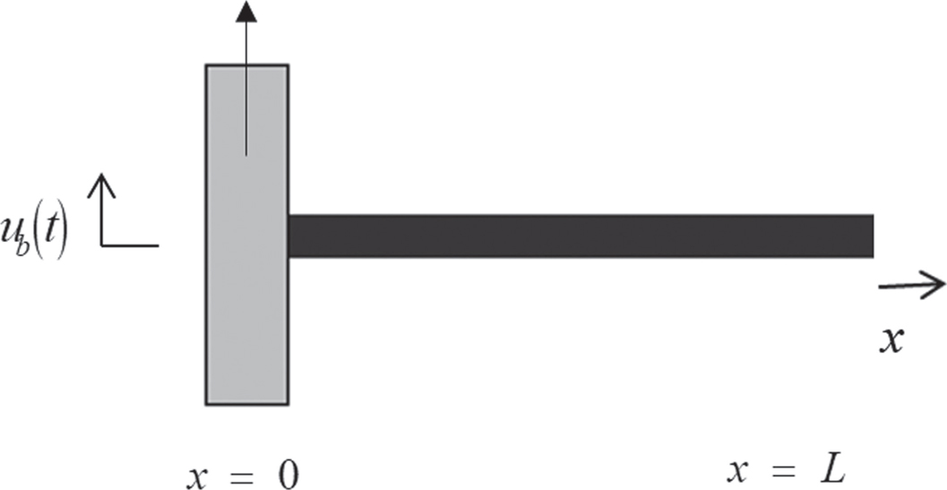
FIGURE 5.3 Cantilever beam excited by the motion to its base in the transverse direction.
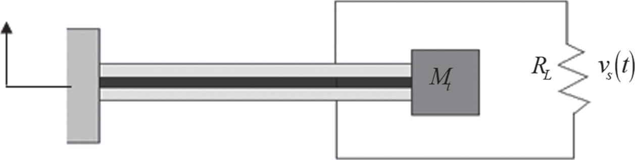
FIGURE 5.4 Bimorph cantilever configurations showing translational base excitation with a series connection.
The natural frequencies of the bimorph with a tip mass can now be calculated from the equation (5.3). The authors considered a smooth radial 195/65R15 91T tire inflated to 220 kPa [2, 3] and found that first mode natural frequency of tire as 515 rad/s. Here a PZT bimorph is designed for this natural frequency. The geometric and material parameters chosen for this design are shown in Tables 5.1 and 5.2.
TABLE 5.1 Geometrical Parameters of Bimorph
| Geometric Parameters | Piezoelectric (PZT-5A) (mm) | Substrate (Brass) (mm) |
| Length, L | 20 | 20 |
| Width, b | 3.39 | 3.39 |
| Thickness, h | 0.13 | 0.08 |
TABLE 5.2 Material Parameters of Bimorph
| Material Parameters | Piezoelectric (PZT-5A) | Substrate (Brass) |
| Mass density, ρ | 7800 kg/m3 | 9000 kg/m3 |
| Young’s modulus, Y | 66 GPa | 105 GPa |
| Piezo. Constant, d31 | –190 pm/V | — |
| Permittivity, ε33 | 1500 ε0 F/m | — |
Brass and PZT-5A are the best options as substrate and piezoelectric material for a bender/bimorph. The bender should fit inside a tiny hollow cylindrical shell, so space constraint for the bender should be considered. We can reduce the length of the bender to make it compact, but the natural frequency will also increase very rapidly; which is not our objective. To reduce the natural frequency we can attach a more weighted tip mass, but it will also increase the volume of tip mass. Due to increased dimensions of tip mass, the bender requires more space for deflection of the bimorph, which will increase the shell size. So the material should be chosen in such a manner that natural frequency should be at the desired value. Thus, the tip mass attached to the bimorph is selected as 1 gm. The given base excitation has an amplitude of 0.1 mm. using the mathematical framework outlined in Erturk and Inman [9–11] expressions for voltage, current, and tip deflection can be derived. The resulting voltage vs. frequency plot is shown in Figure 5.5.
FIGURE 5.5 Voltage vs. frequency of the bimorph at first mode of frequency at 35 kΩ of load resistance for 195/65R15 91T tire.
The tip deflection is shown in Figure 5.6. Further analysis can be carried out by changing the load resistance and such sensitivity analyses are needed for the final design of the piezo harvester.
5.8 ECONOMIC AND ENVIRONMENTAL ANALYSIS
Safety is the prime motivation for the development of TPMS. The main goal is to reduce the number of accidents occurring every year. The use of TPMS in vehicles can also improve fuel economy and mileage. The US Department of Energy estimated that one psi (pound per square inch) drop in tire pressure is lowering the mileage by 0.4% [12]. This small loss for one vehicle becomes very large when it is multiplied with all running vehicles over a period of time. The estimates show that in the US alone, approximately 100,000,000 cars filling up once per week can save almost 170,000,000 barrels of oil per year by maintaining specified tire pressure. Tests show that visual inspection to judge the specified tire pressure is not reliable.
FIGURE 5.6 Tip deflection of the harvester at first mode of frequency at 35 kΩ of load resistance for 195/65R15 91T tire.
The batteries used in TPMS have a negative environmental impact. The NHTSA estimated a 2% increase in US battery usage. Approximately 71 million tiny batteries are used in the TPMS. But TPMS benefits the environment by saving extra fuel lost due to under-inflation of tire i.e., reduce emission, so a smaller overall increase in battery volume may be justified [4]. Even this battery volume and chemical content can be nullified if we move to piezoelectric harvester operated TPMS. The NHTSA estimates that TPMS saves 660 lives per year, as well as preventing 33,000 injuries and saving $511 million worth of gas [5].
The cost of piezoelectric bimorphs and associated electronics is dropping significantly over the years. As per a roadmap of Freescale the fifth generation TPMS may have energy harvesting capability. Development of a highly miniaturized Tire Pressure Monitoring System for in-tire assembly with volume < 1 cm3 and mass < 5 gm with MEMS piezo energy harvester is being pursued by a consortium led by Infineon [6]. New piezo materials developed [7, 8, 13] and mass production of piezo devices may make TPMS affordable for all vehicles.
KEYWORDS
• commercially off the shelf
• National Highway Traffic Safety Administration
• piezoelectric energy harvester
• radio frequency
• tire pressure maintenance system
• tire pressure monitoring sensor
REFERENCES
1.Joe, W., (2012). Tire Pressure Affects Stopping Distance, Fuel Economy. http://www.newsday.com/classifieds/cars/tire-pressue-affects-stopping-distance-fuel-economy-1.3760110 (accessed on 13 May 2020).
2.Hans, P., (2012). Tire and Vehicle Dynamic. SAE International, Elsevier, ISBN: 978–0-08–097016–5.
3.Koizumi, T., Tsujiuchi, N., Matsubara, M., & Nakamura, F., (2010). Vibration Analysis of Rolling Tire Based on Thin Cylindrical Shell Theory. Toyo tire and rubber Co., LTD, ISMA.
4.Skip, S., (2011). Changing TPMS Sensor Batteries. https://www.tirereview.com/changing-tpms-sensor-batteries/ (accessed on 13 May 2020).
5.Sean, P., (2014). TPMS Advantages and Disadvantages. https://www.tirereview.com/author/sean_phillips/ (accessed on 13 May 2020).
6.Thomas, H., et al., (2008). An Energy Harvesting System for in-tire TPMS. Collaborative effort between Infineon Austria, Infineon Norway, TU Vienna, Vestfold University College, SINTEF, PwrSoC Workshop.
7.Narayan, K., (2017). M. Tech Thesis. IIT Jodhpur, Energy Harvesting through Piezoelectricity and its Application in TPMS.
8.Roger, A., (2009). Energy Harvesting Looks to Solve Critical TPMS Issues. http://electronicdesign.com/energy/energy-harvesting-looks-solve-critical-tpms-issues (accessed on 13 May 2020).
9.Alper, E., & Denial, I., (2008). A distributed parameter electromechanical model for cantilevered piezoelectric energy harvesters. Journal of Vibration and Acoustics.
10.Alper, E., & Denial, I., (2009). An experimentally validated bimorph cantilever model for piezoelectric energy harvesting from cantilevered beams. Smart Mater. Struct., 18(025009), p. 18.
11.Alper, E., & Denial, J. I., (2011). Piezoelectric Energy Harvesting. John Wiley & Sons, ISBN: 978-0-470-68254-8.
12.How Tire Pressure Affects MPG, (2015). http://procarmechanics.com/how-tire-pressure-affects-mpg/ (accessed on 13 May 2020).
13.Shashank, P., & Inman, D. J., (2009). Energy Harvesting Technologies. Springer, ISBN: 978-0-387-76463-4.