CHAPTER 13
Mechanical Design of a Slider-Crank Mechanism for a Knee Orthotic Device Using the Jaya Algorithm
Department of Mechanical Engineering, Manipal University Jaipu, Jaipur, Rajasthan, India,
ramanpreet.singh@jaipur.manipal.edu (R. Singh)
13.1 INTRODUCTION
Human gait is a complex function that requires repetitive and coordinated rhythmic movement of lower-limbs. Its control is dependent on the coordination of the musculoskeletal system, locomotion mechanism, and motor control. Any disturbance in their coordination may lead to stroke. Stroke destroys many the cortical neurons whereas remaining neurons are temporarily affected. The temporarily affected neurons may regain functioning to some extent. Therefore, post-stroke patients are suggested to undergo rehabilitation and try to relearn walking. Typically, this is done with the help of manual physiotherapies and with assistive devices [1, 2]. Traditional therapies are done manually with the help of therapists, treadmills, bodyweight support systems, etc. However, they are physically demanding for therapists. Also, frequent and consistent training sessions may not be available which may leave a patient with permanent disability [3].
Various treadmill-based exoskeletons have been explored over the years. Typically, these are multi-degree of freedom (DF) devices that contain mechanisms, actuators, and control technology for manipulating users’ lower limb motion while walking. Some of the treadmill-based rehabilitation devices are discussed here. The ReoAmbulatorTM which is commercialized by Motorika USA Inc. powered to lift a patient from a wheelchair and transports the patient over the treadmill [4]. Lokomat is developed from the prototype of driven gait orthosis and it is provided with virtual reality environment along with audio and visual biofeedback which is commercially available [5] while driven gait orthosis [6], LokoHelp [7], Alex [8], and Lopes [9] are among other treadmill-based rehabilitation devices. Also, the treadmill-based exoskeletons are bulky and they are often used in rehabilitation centers and hospitals. The other categories of exoskeletons may be over-ground and portable exoskeletons. The mobile base over-ground rehabilitation exoskeletons may consist of a mobile base, a BWS, and joint level assistance to provide comfort to the patients for rehabilitation. They do not restrict training to the treadmill or a confined area rather they allow patients to regain their natural walk. In addition, the patients move voluntarily despite considering a predetermined pattern for moving. Some of the over-ground exoskeletons are explored to identify the mechanism used for the joints. EXPOS developed by Sogang University is used especially for the elderly and the patients [10]. Another version of the EXPOS which is known as SUBAR (Sogang University biomedical assistive robot) may also be used for over-ground rehabilitation [11]. LEER (lower extremity exoskeleton robot) [12], NatTUre-gaits [13], WalkTrainerTM [14], and Kine Assist robotic device [15] are among other rehabilitation devices which may also be used.
Another category of lower-limb robotic devices is portable rehabilitation exoskeletons or assistive devices. These exoskeletons are mobile and do not require any base or treadmill. As opposed to treadmill-based exoskeletons, they are lightweight and easy to don and doff. Their simple and small structure makes them relatively more comfortable in comparison with treadmill-based and mobile-based overground exoskeletons. Besides, one of the most notable features of the portable exoskeletons is that they allow natural walking, and the power source is attached to the exoskeleton for actuating the joints. In addition, the users require crutches along with the exoskeleton during walking, because of their impaired physical ability. Some of these portable multi-DOF exoskeletons are explored here. ReWalk [16] and HAL [17] are the commercially available portable exoskeletons that can be used with crutches for rehabilitation. Other portable rehabilitation devices developed by researchers include Powered Orthosis of Vanderbilt University [18], modified motor-powered gait orthosis [19], powered gait orthosis (PGO) [20], knee-ankle-foot robot [3], etc.
It is found that linkage mechanisms play a vital role in the actuation of mechanism, gait speed, step length, etc. Hence, it is also worthwhile to investigate the area of assisting devices or orthosis for knee joint while synthesizing a mechanism for supporting an injured knee, or gait rehabilitation. Typically, it is used to correct the functions of physically impaired patients. Some of the important features of an orthosis are restraining joint mobility, correcting limb malformations, assistance in ambulation, stability, etc. [21]. Various orthoses that are used for assisting an injured knee or rehabilitating gait are explored. The orthosis/ knee brace uses a three-point fixation system to avoid hyperextension and effectively control hyperextension [22]. Another device is an off-the-shelf knee brace with a hinged between the thigh and shank which can be used by osteoarthritis patients [23]. Another orthosis that can be used for providing relief to osteoarthritis patients can be an adjustable unloader knee brace which uses a polycentric joint between thigh and leg segments. In addition, this novel knee brace does not require straps for providing the needed moment [24].
Besides, the orthoses can be extended to ankle and foot and those types of orthoses are called knee-ankle-foot orthoses (KAFO). KAFO contains a cam mechanism with friction rings and lock that enable the KAFO to lock the knee joint at any position to assist the patients with knee flexion contractures [25]. Another KAFO uses a four-bar linkage for coupling the knee and ankle movement [26]. In addition, actuators with linkage mechanism at the knee joints are also found [27–29]. A four-bar linkage actuator for knee assisting devices can be used to mimic the motion of the human knee joint for the rehabilitation of hemiplegic patients [30]. Devices which couple the knee and ankle movement through linkage mechanisms and which use linkage mechanisms for actuation are among others. Thus, the mechanisms play a vital role in the functioning of the exoskeleton and assisting devices. A mechanism can be employed in rehabilitation devices, bipeds, exoskeletons, etc.
Single DF walking mechanism is another area in which researchers are working actively. Various synthesis techniques and mechanisms have been explored for designing them. A cam-driven mechanism in which a cam system attached to the body frame connects the feet of the robot through a pantograph mechanism that can be used [31]. A six-bar linkage can be used to approximate the femur and tibia motions while a third leg can be included to ensure the frontal stability [32]. Alternatively, a six-bar Stephenson III mechanism can be used for designing a walking linkage. The mechanism can be synthesized in two stages; four-bar linkage that generates the inverted gait should be synthesized in the first stage followed by the synthesis of a dyad that inverts and magnify the gait [33]. Another six-bar linkage, i.e., Klann linkage can also be used for producing a variety of gaits [34].
It is found that most of the devices are treadmill-based gait rehabilitation systems, overground, and portables devices that have multi-degrees of freedom, in addition, they use a single-axis, revolute joint at the knee, which allows only rotational motion. The devices that use linkage mechanisms at the knee, hip, ankle, and foot are rare and they require the large value of peak torque to their actuation design. Therefore, in this chapter, an optimized design of the slider-crank knee orthotic device is proposed. Its mechanical design is inspired from the design of a compact portable knee-ankle-foot robot which can be referred in detail from Ref. [3].
The remainder of the chapter is structured as follows. Section 13.2 discusses the biomechanics of the human knee joint. Section 13.3 illustrates the mechanism design and optimization problem formulation. The optimization algorithm required to solve the optimization problem is presented in Section 13.4. Lastly, conclusions are outlined in Section 13.5.
13.2 BIOMECHANICS OF HUMAN KNEE
Comprehension of physiological gait patterns is crucial for defining the trajectories to guide walking. Human walking (gait) pattern varies with individuals; hence, it should be studied for many subjects. The kinematics and kinetics data for human gait can be obtained from the normative gait database [35, 36]. Typically, it is presented in a statistical average and standard deviation of several sets of values normalized for a complete gait cycle. The measurement techniques and subjects may differ for distinct research groups; therefore, the reported data may differ. Figures 13.1 and 13.2 demonstrate the biomechanics of the human lower limb in terms of knee flexion/extensions and torques.
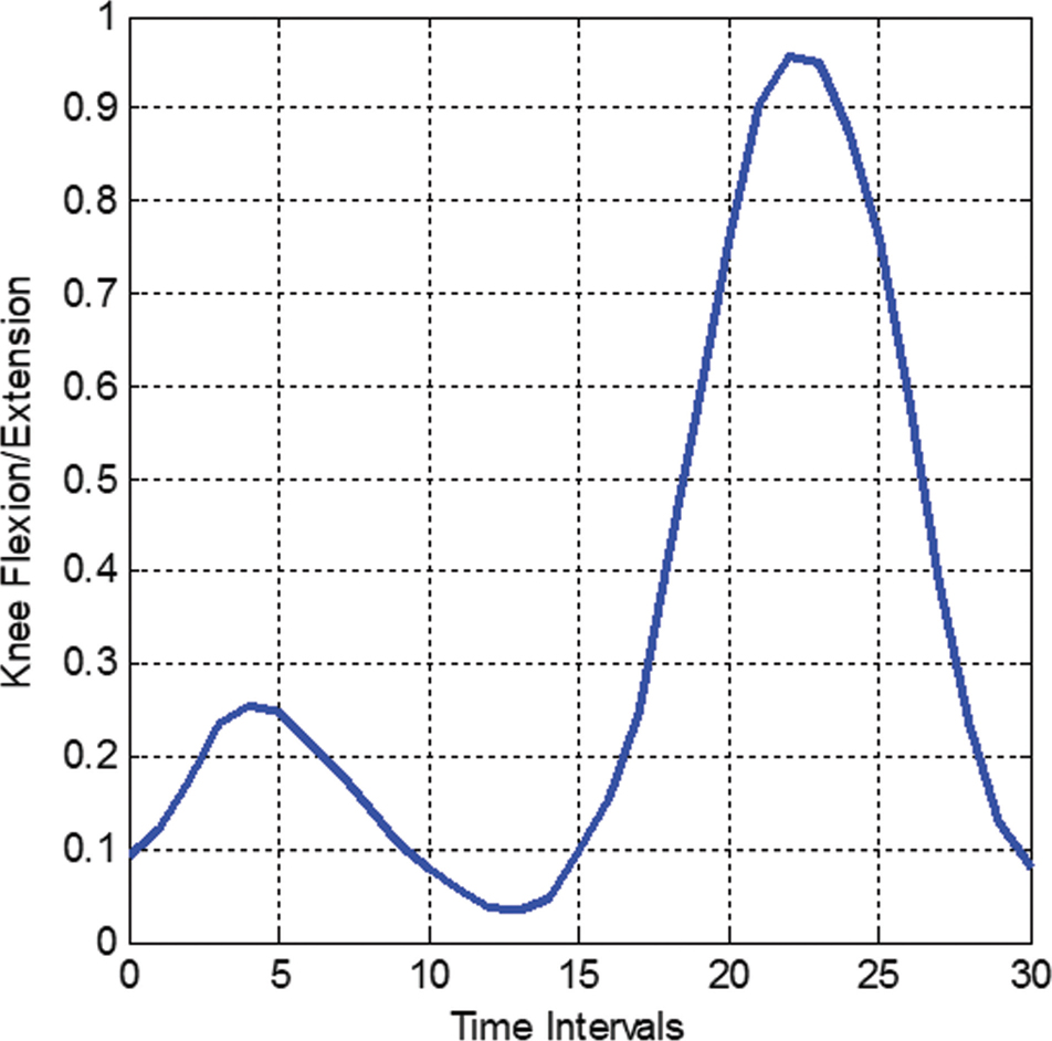
FIGURE 13.1 Average knee flexion/extension.
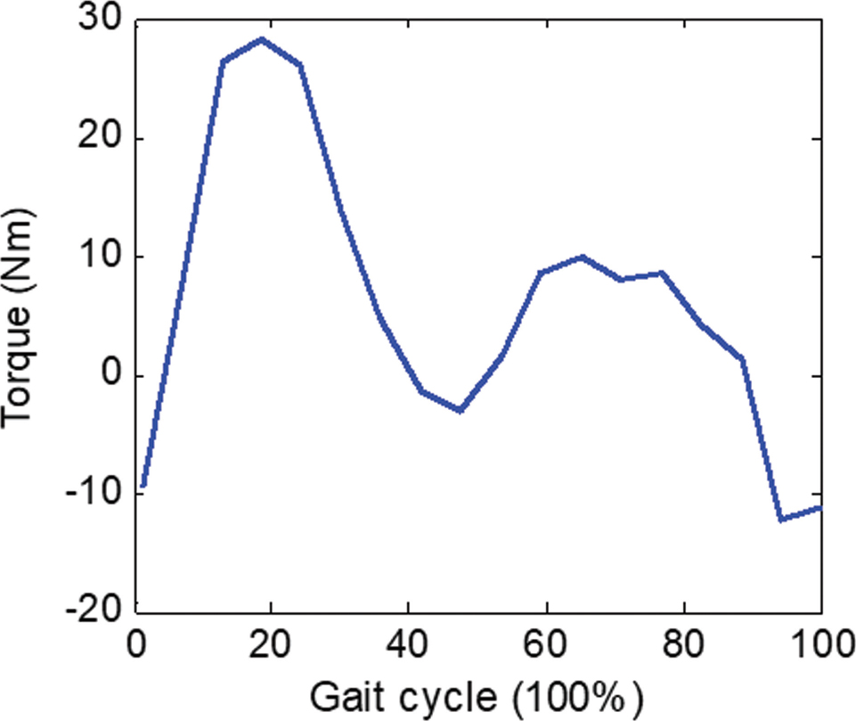
FIGURE 13.2 Joint torque.
13.3 MECHANISM DESIGN AND OPTIMIZATION PROBLEM FORMULATION
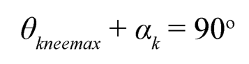
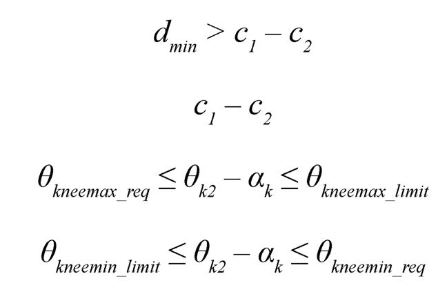
A slider-crank mechanism is used in this design for the knee joint. The Schematic diagram of the slider-crank mechanism for the orthotic knee joint is shown in Figure 13.4. An optimization problem is formulated to minimize the required peak force by the actuator. To obtain an adequate and safe motion range, the physical structure and geometrical constraints are adapted from Ref. [3]. Figures 13.3 and 13.4 show various definitions of the slider-crank mechanism for the knee joint. is the crank angle when the relative angle between femur and tibia, θknee, becomes 0. Also, to ensure that at the peak value of the required torque the crank and connecting rod becomes perpendicular, consequently, it maximizes the length of the lever-arm to apply force a constraint is used as follows:
 (13.1)
In which, θkneemax represents knee joint orientation corresponding to maximum torque.
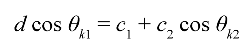
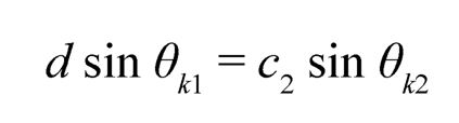
To optimize the geometrical parameters of the four-bar slider-crank mechanism, and to ensure the allowable range of motion, following kinematics of the slider-crank mechanism is considered:
 (13.2)
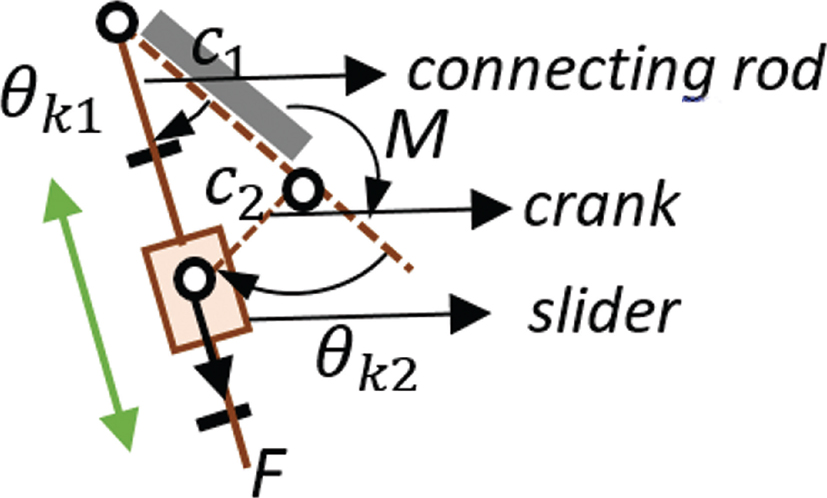
FIGURE 13.3 Various definitions of slider-crank mechanism.
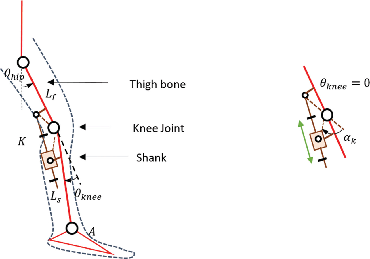
FIGURE 13.4 Schematic of the orthotic knee joint with the slider-crank mechanism.
 (13.3)
where, 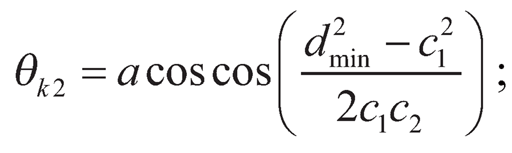 ; also θk2 = αk+ θknee
The torque generated at the knee joint can be posed as:
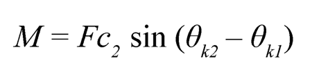 (13.4)
Since the only unknown in Eq. (13.4) is. Therefore, it is posed as minimization of peak actuator force problem in the form of an infinite norm, as follows:
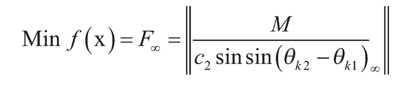
The geometrical constraints for the above objective function can be posed as follows, as in Ref. [3]:
Subject to dmax< c1+ c2
13.4 OPTIMIZATION ALGORITHM AND RESULTS
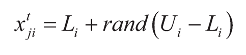
In this section, an optimization algorithm, Jaya, is used to solve the problem formulated in the previous section (as adopted from Ref. [3]). Jaya [37] is a simple algorithm that tries to move the candidate solution towards the best candidate and away from the worst candidate.
The algorithms begin with the random population initialization using Eq. (135) in which xtij, is the jth candidate for j = 1,…, c, that contains design variables (i = 1,… d). Li and Ui are the lower and upper limits on the ith design variable and t represents tth iteration.
 (13.5)
From the population of candidates, best, and worst candidates are identified. These best and worst candidates are utilized to move the candidate solution towards the best and away from the worst solution. This can be achieved by using Eq. (13.6) as follows:
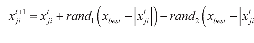 (13.6)
In which, rand1 and rand2 are the random numbers between [0, 1].
The updated population of the candidates is then compared with the previous population of candidates. A new population is formed by the greedy selection of candidates between two populations. Lastly, the termination criterion is checked and this step completes the first iteration of Jaya algorithm. The details of the Jaya algorithm are provided in Figure 13.5.
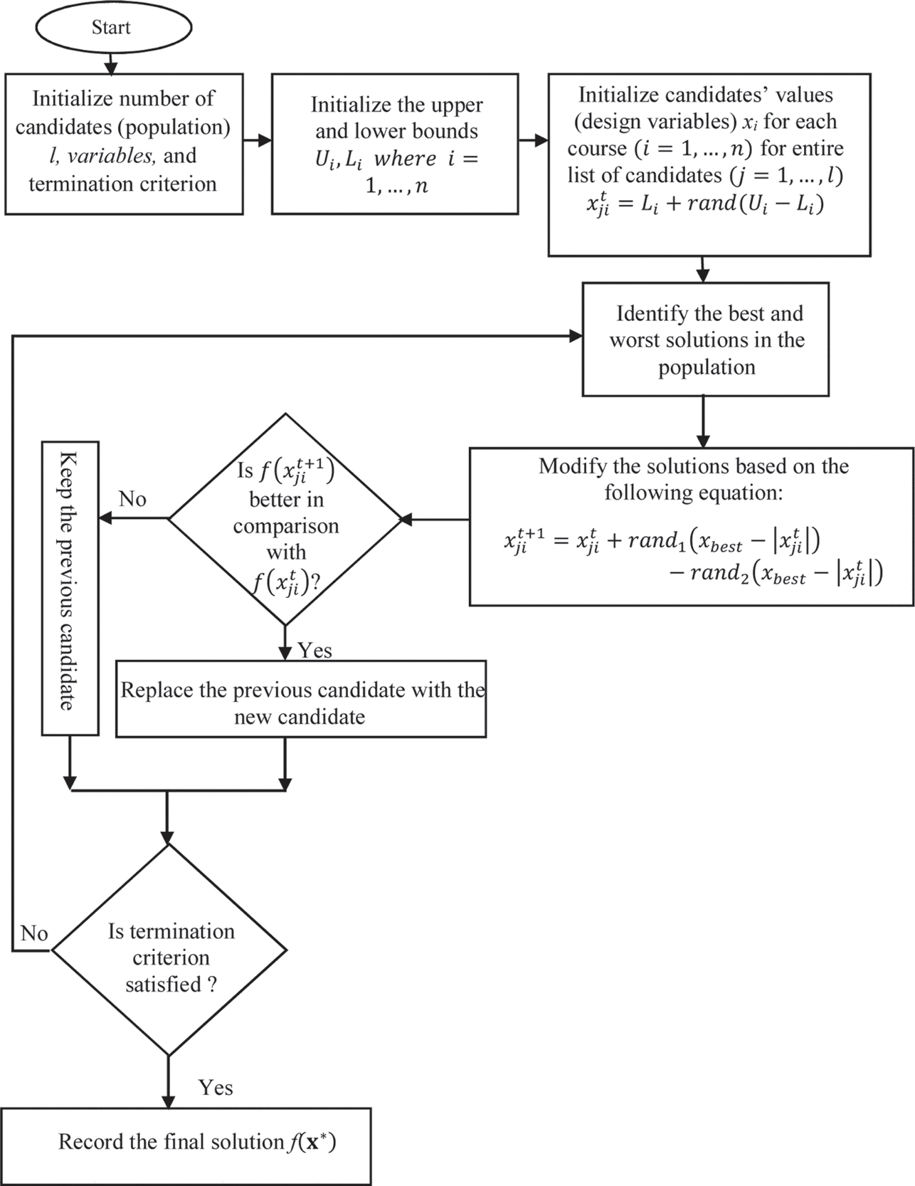
FIGURE 13.5 Flowchart of the Jaya algorithm.
The algorithm is implemented to minimize peak force for the design of a slider-crank mechanism. The algorithm helped in reducing the required actuator force. The results of the new design after optimization are presented in Table 13.1.
TABLE 13.1 Optimized Parameters of Robotic Knee Joint
| Parameters | Knee Joint [3] | Knee Joint Proposed |
| Initial Angle ak (degrees) | 70 | 73.17 |
| θekneemix_req θkneemax_req (limiting range) | 0–120 | 8.67–74 |
| c1 (mm) | 168 | 177.6 |
| c2 (mm) | 45 | 53 |
| Peak Force (N) | 687 | 554.176 |
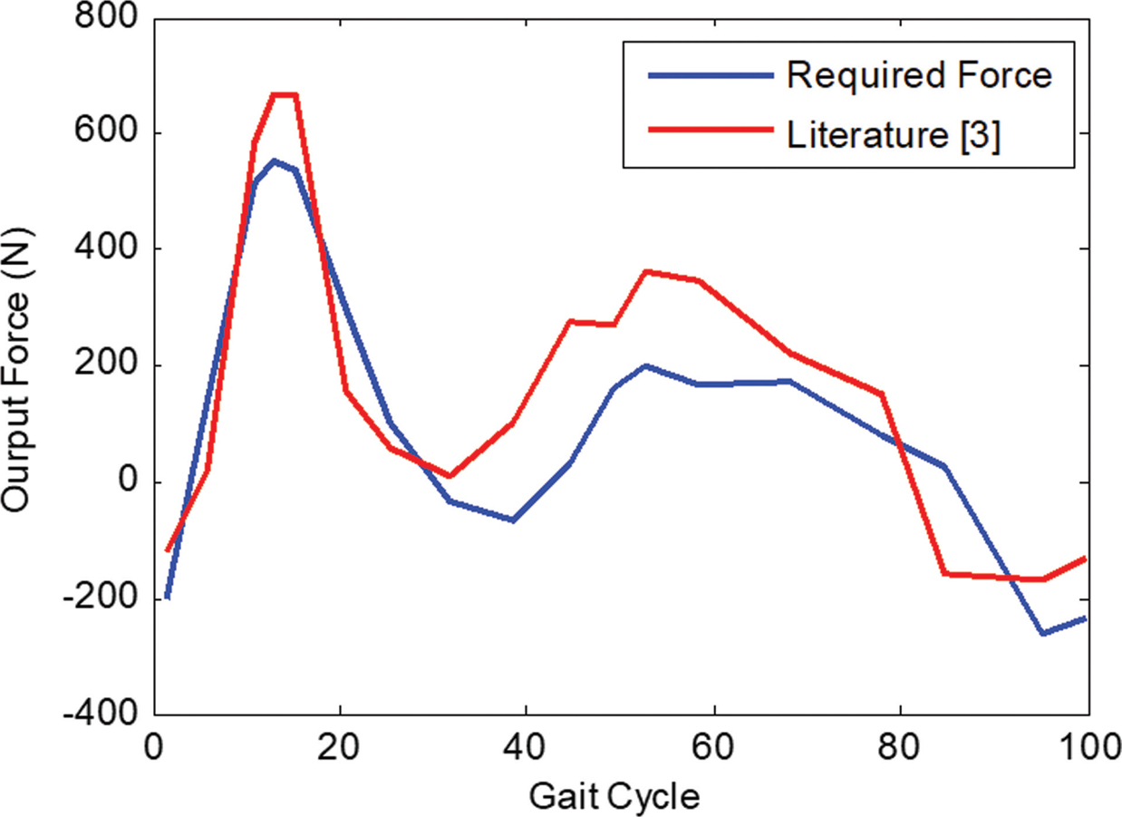
FIGURE 13.6 Required output force.
Figure 13.6 shows the comparison between the required output forces by the slider-crank mechanism with that of the mechanism presented in Ref. [3]. It is found that there is a reduction of 19% in the required peak force using the proposed slider-crank mechanism in the orthotic device.
13.5 CONCLUSIONS
The chapter proposed a slider-crank linkage for an orthotic device that required less peak force for actuation. The mechanism is synthesized using the optimal synthesis technique. An optimization inspired problem and geometrical constraints are formulated based on the notion presented in the literature. A metaphor-less algorithm, Jaya, is used to solve the optimization problem. It is found that the required peak force has reduced to around 19% of the peak force presented in the literature. The proposed slider-crank mechanism can be used for the orthotic devices to provide support to the injured knee joint.
KEYWORDS
• biomechanics
• knee-ankle-foot orthoses
• lower extremity exoskeleton robot
• optimization algorithm
• powered gait orthosis
• Sogang University biomedical assistive robot
REFERENCES
1. Kora, K., Stinear, J., & McDaid, A., (2017). Design, analysis, and optimization of an acute stroke gait rehabilitation device. Journal of Medical Devices, 11(1), 014503.
2. Langhorne, P., Stott, D., Knight, A., Bernhardt, J., Barer, D., & Watkins, C., (2010). Very early rehabilitation or intensive telemetry after stroke: A pilot randomized trial. Cerebrovascular Diseases, 29(4), 352–360.
3. Chen, G., Qi, P., Guo, Z., & Yu, H., (2016). Mechanical design and evaluation of a compact portable knee-ankle-foot robot for gait rehabilitation. Mechanism and Machine Theory, 103, 51–64.
4. West, R. G., (2004). Inventor; Health South Corporation, assignee. Powered Gait Orthosis and Method of Utilizing Same. United States patent US 6,689,075.
5. Riener, R., Lunenburger, L., Jezernik, S., Anderschitz, M., Colombo, G., & Dietz, V., (2005). Patient-cooperative strategies for robot-aided treadmill training: First experimental results. IEEE Transactions on Neural Systems and Rehabilitation Engineering, 13(3), 380–394.
6. Colombo, G., Joerg, M., Reinhard, S. B. N., & Dietz, V., (2000). Treadmill training of paraplegic patients using a robotic orthosis. Development, 37(6), 693–700.
7. Freivogel, S., Mehrholz, J., Husak-Sotomayor, T., & Schmalohr, D., (2008). Gait training with the newly developed ‘Loko Help’-system is feasible for non-ambulatory patients after stroke, spinal cord, and brain injury: A feasibility study. Brain Injury, 22(7–8), 625–632.
8. Banala, S. K., Agrawal, S. K., & Scholz, J. P., (2007). Active leg exoskeleton (ALEX) for gait rehabilitation of motor-impaired patients. In: Rehabilitation Robotics (pp. 401–407). ICORR 2007, IEEE 10th International Conference on 2007 Jun 13 IEEE.
9. Veneman, J. F., Kruidhof, R., Hekman, E. E., Ekkelenkamp, R., Van, A. E. H., & Van, D. K. H., (2007). Design and evaluation of the LOPES exoskeleton robot for interactive gait rehabilitation. IEEE Transactions on Neural Systems and Rehabilitation Engineering, 15(3), 379–386.
10. Kong, K., & Jeon, D., (2006). Design and control of an exoskeleton for the elderly and patients. IEEE/ASME Transactions on Mechatronics, 11(4), 428–432.
11. Kong, K., Moon, H., Hwang, B., Jeon, D., & Tomizuka, M., (2009). Impedance compensation of SUBAR for back-drivable force-mode actuation. IEEE Transactions on Robotics, 25(3), 512–521.
12. Guo, Z., Fan, Y., Zhang, J., Yu, H., & Yin, Y., (2012). A new 4M model-based human-machine interface for lower extremity exoskeleton robot. In: International Conference on Intelligent Robotics and Applications (pp. 545–554). Springer, Berlin, Heidelberg.
13. Wang, P., Low, K. H., & Tow, A., (2011). Synchronized walking coordination for impact-less footpad contact of an overground gait rehabilitation system: NaTUre-gaits. In: Rehabilitation Robotics (ICORR) (pp. 1–6). IEEE International Conference on 2011 Jun 29. IEEE.
14. Bouri, M., Stauffer, Y., Schmitt, C., Allemand, Y., Gnemmi, S., Clavel, R., Metrailler, P., & Brodard, R., (2006). The walk trainer: A robotic system for walking rehabilitation. In: Robotics and Biomimetics (pp. 1616–1621). ROBIO’06, IEEE International Conference on 2006 Dec. 17. IEEE.
15. Peshkin, M., Brown, D. A., Santos-Munné, J. J., Makhlin, A., Lewis, E., Colgate, J. E., Patton, J., & Schwandt, D., (2005). Kine assists: A robotic overground gait and balance training device. In: Rehabilitation Robotics (pp. 241–246). ICORR 2005, 9th International Conference on 2005 Jun 28. IEEE.
16. Zeilig, G., Weingarden, H., Zwecker, M., Dudkiewicz, I., Bloch, A., & Esquenazi, A., (2012). Safety and tolerance of the ReWalkTM exoskeleton suit for ambulation by people with complete spinal cord injury: A pilot study. The Journal of Spinal Cord Medicine, 35(2), 96–101.
17. Kawamoto, H., Hayashi, T., Sakurai, T., Eguchi, K., & Sankai, Y., (2009). Development of single leg version of HAL for hemiplegia. In: Engineering in Medicine and Biology Society (pp. 5038–5043). EMBC 2009, Annual International Conference of the IEEE 2009 Sep. 3. IEEE.
18. Quintero, H., Farris, R., Hartigan, C., Clesson, I., & Goldfarb, M., (2011). A powered lower limb orthosis for providing legged mobility in paraplegic individuals. Topics in Spinal Cord Injury Rehabilitation, 17(1), 25–33.
19. Ohta, Y., Yano, H., Suzuki, R., Yoshida, M., Kawashima, N., & Nakazawa, K., (2007). A two-degree-of-freedom motor-powered gait orthosis for spinal cord injury patients. Proceedings of the Institution of Mechanical Engineers, Part H: Journal of Engineering in Medicine, 221(6), 629–639.
20. Ruthenberg, B. J., Wasylewski, N. A., & Beard, J. E., (1997). An experimental device for investigating the force and power requirements of a powered gait orthosis. Journal of Rehabilitation Research and Development, 34(2), 203.
21. Masiero, S., Mastrocostas, M., & Musumeci, A., (2018). Orthoses in older patients. In: Rehabilitation Medicine for Elderly Patients (pp. 133–145). Springer, Cham.
22. Butler, P. B., Evans, G. A., Rose, G. K., & Patrick, J. H., (1983). A review of selected knee orthoses. Rheumatology, 22(2), 109–20.
23. Draganich, L., Reider, B., Rimington, T., Piotrowski, G., Mallik, K., & Nasson, S., (2006). The effectiveness of self-adjustable custom and off-the-shelf bracing in the treatment of varus gonarthrosis. Jbjs, 88(12), 2645–52.
24. Hangalur, G., Bakker, R., Tomescu, S., & Chandrashekar, N., (2018). New adjustable unloader knee brace and its effectiveness. Journal of Medical Devices, 12(1), 015001.
25. Jonathan, K. P. E., (2009). PhD engineering design review of stance-control knee-ankle-foot orthoses. Journal of Rehabilitation Research and Development, 46(2), 257.
26. Berkelman, P., Rossi, P., Lu, T., & Ma, J., (2007). Passive orthosis linkage for locomotor rehabilitation. In: Rehabilitation Robotics (pp. 425–431). ICORR 2007, IEEE 10th International Conference on 2007 Jun 13. IEEE.
27. Singh, R., Chaudhary, H., & Singh, A. K., (2017). Defect-free optimal synthesis of crank-rocker linkage using nature-inspired optimization algorithms. Mechanism and Machine Theory, 116, 105–122.
28. Singh, R., Chaudhary, H., & Singh, A. K., (2018). A novel gait-based synthesis procedure for the design of 4-bar exoskeleton with natural trajectories. Journal of Orthopaedic Translation, 12, 6–15.
29. Singh, R., Chaudhary, H., & Singh, A., (2019). A novel gait-inspired four-bar lower limb exoskeleton to guide the walking movement. Journal of Mechanics in Medicine and Biology, 1950020.
30. Kim, J. H., Shim, M., Ahn, D. H., Son, B. J., Kim, S. Y., Kim, D. Y., Baek, Y. S., & Cho, B. K., (2015). Design of a knee exoskeleton using foot pressure and knee torque sensors. International Journal of Advanced Robotic Systems, 12(8), 112.
31. Zhang, Y., Arakelian, V., & Le Baron, J. P., (2017). Design of a legged walking robot with adjustable parameters. In: Advances in Mechanism Design II (pp. 65–71). Springer International Publishing.
32. McKendry, J., Brown, B., Westervelt, E. R., & Schmiedeler, J. P., (2008). Design and analysis of a class of planar biped robots mechanically coordinated by a single degree of freedom. Journal of Mechanical Design, 130(10), 102302.
33. Batayneh, W., Al-Araidah, O., & Malkawi, S., (2013). Biomimetic design of a single DOF Stephenson III leg mechanism. Mechanical Engineering Research, 3(2), 43.
34. Sheba, J. K., Elara, M. R., Martínez-García, E., & Tan-Phuc, L., (2017). Synthesizing reconfigurable foot traces using a Klan mechanism. Robotica, 35(1), 189–205.
35. Majernik, J., (2013). Normative human gait databases. Statistics Research Letters, 2(3), 69–74.
36. Perry, J., & Davids, J. R., (1992). Gait analysis: Normal and pathological function. Journal of Pediatric Orthopaedics, 12(6), 815.
37. Rao, R., (2016). Jaya: A simple and new optimization algorithm for solving constrained and unconstrained optimization problems. International Journal of Industrial Engineering Computations, 7(1), 19–34.